Do you have a question about the York SSS 7L-B and is the answer not in the manual?
Explains how revisions are indicated in the document.
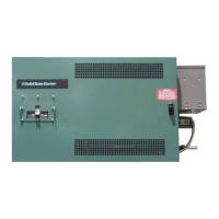
Provides an overview of the Style B LCSSS and its features.
Explains the soft start operation and SCR phase-back technique.
Details the backup protection and communication checks for system microprocessors.
Explains how the starter's SCRs are cooled using a water-to-water heat exchanger.
Discusses AC power line voltage requirements and phase rotation for proper operation.
Details circuits that protect the motor from high current and other fault conditions.
Introduces the new Logic/Trigger Board and its integration of functions.
Explains how the Logic/Trigger Board determines starter size and scales current via jumpers.
Describes the function of the two LEDs on the Logic/Trigger Board for serial link verification.
Explains the functions of relays K1 and K2 for shutdown signals and coolant pump control.
Details the sequence of events when a safety shutdown is generated by the Logic/Trigger Board.
Explains the shutdown condition for motor current exceeding 105% of FLA for a sustained period.
Describes the shutdown triggered by SCR heatsink temperatures exceeding 212°F.
Details the shutdown condition for motor current exceeding a peak starting current threshold.
Explains the shutdown when an SCR fails to turn on or is detected as open for 5 consecutive seconds.
Details the shutdown for significant imbalance between motor current phases.
Describes the shutdown for incorrect AC input phase rotation detected during initial startup.
Explains the shutdown when an SCR is detected as shorted.
Outlines the sequence of events when a cycling shutdown occurs.
Details the shutdown for input line voltage exceeding thresholds for 20 continuous seconds.
Describes the shutdown when the OptiView Control Center fails to communicate with the Logic/Trigger Board.
Explains the shutdown if current transformers are not properly connected or sized.
Indicates a shutdown if power is not properly applied to the logic board.
Details the shutdown if the microprocessor and DSP lose communication.
Describes the shutdown when SCR heatsink temperatures fall below a specified low threshold.
Details the shutdown for input line voltage falling below thresholds for 20 continuous seconds.
Explains shutdown if synchronization between the SCR firing and AC voltage is lost.
Describes shutdown if any input phase voltage drops below a threshold.
Details shutdown due to momentary motor current interruption or transient torque conditions.
Explains shutdown if the start signal from the OptiView Control Center is not received.
Describes shutdown if communication link between OptiView and Logic/Trigger board fails.
Explains shutdown if the K1 relay contacts, indicating a stopped state, are open without a fault.
Details the condition where SCRs are too hot to start, preventing operation until cooled.
Lists essential steps and checks before starting the chiller and LCSSS.
Provides the procedure for filling the starter's closed loop cooling system with proper coolant.
Explains how to manually operate the closed loop coolant pump for testing or maintenance.
Details the importance and procedure for regular coolant changes to prevent corrosion.
Provides steps to diagnose why the closed loop coolant pump is not functioning.
Guides service technicians on how to approach troubleshooting the LCSSS.
Provides steps to test if an SCR assembly is shorted using an ohmmeter.
Details how to test the SCR gate for open or shorted conditions.
Explains how to test the gate driver output for proper voltage and resistance.
Guides on verifying if current imbalances are real or due to reporting issues.
Provides steps to identify and troubleshoot false current imbalance reporting.
Details the procedure for safely removing SCR assemblies for replacement.
Explains the steps for installing new SCR assemblies, including connections and torque.