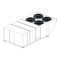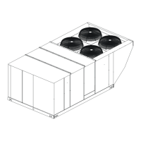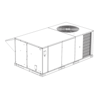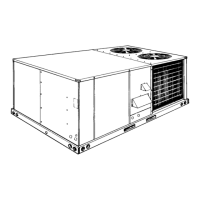
Do you have a question about the York SUNLINE MagnaDRY DR180 and is the answer not in the manual?
| Brand | York |
|---|---|
| Model | SUNLINE MagnaDRY DR180 |
| Category | Air Conditioner |
| Language | English |
Discusses hazards of installation and servicing by unqualified personnel.
Instructions for inspecting the unit for transit damage and reporting it.
Lists additional information sources for design, installation, operation, and service.
Refers to a specific maintenance and service information manual for parts.
Lists design certifications by CSA for various unit configurations and installation types.
General safety precautions and warnings for installing the unit.
Lists national and local safety codes that must be followed during installation.
Guidelines for selecting a suitable outdoor location for the unit.
Instructions and precautions for lifting and moving the unit safely.
Required clearances for proper operation, service, and combustion air.
Guidance on designing and sizing ductwork according to ACCA standards.
Instructions for installing the fixed outdoor air intake damper assembly.
Instructions for plumbing the condensate drain line, including trapping.
Information about factory-adjusted compressor mountings and not loosening bolts.
Details on supplied filters, conversion to four-inch filters, and maintenance.
Lists the removable panels providing access to various unit components.
Guidelines for locating and installing the room thermostat.
Requirements for field wiring, grounding, and power supply.
Information on factory-installed electric heaters, power supply, and CFM limitations.
Details on gas-fired heaters, conversion to L.P. gas, and application data.
Guidance on proper gas piping sizing and installation according to codes.
Instructions for routing the gas supply line and typical piping arrangements.
Information on converting units for L.P./Propane gas and operational requirements.
Instructions for installing vent and combustion air hoods for proper unit function.
Refers to instructions for field assembly of an economizer rain hood.
Refers to instructions for installing power exhaust/barometric relief damper and rain hood.
Details on adjusting economizer and power exhaust damper setpoints.
Information on indoor air quality sensor inputs and their effect on damper modulation.
Overview of how thermostat calls control unit operations for heating and cooling.
Supply air blower operates continuously during cooling or heating cycles.
Blower operates only when cooling or heating is requested.
Cooling operation when no outdoor air intake is used.
Economizer operation with a single enthalpy sensor.
Economizer operation with dual enthalpy sensors for maximum efficiency.
Economizer operation combined with a power exhaust system.
Explains operation of motorized outdoor air dampers when "R" to "G" circuit is complete.
Describes unit response to high-pressure limit switch opening during cooling.
Describes unit response to low-pressure limit switch opening during cooling.
Describes unit response to freezestat opening during cooling operation.
Details operation of the unit in low ambient cooling mode with defrost cycle.
Lists safety controls monitored by the unit control board for cooling systems.
Describes the normal mode of reheat operation for dehumidification.
Describes the alternate mode of reheat operation for dehumidification.
Describes how the UCB reacts to temperature limit switches during heating.
Lists safety controls monitored by the UCB for electric heat units.
Mentions flash codes for errors and refers to a table.
How to reset heating flash codes by lowering the thermostat.
Importance of correct heat anticipator setpoints for cycle length and temperature swing.
How the UCB reacts to temperature limits during gas heating.
How the UCB monitors the gas valve and its response to voltage signals.
Lists safety controls monitored by the UCB for gas furnace units.
List of checks to perform before starting the unit for cooling.
Steps to follow for operating the unit in cooling mode.
List of checks to perform after the unit has started in cooling mode.
Checks to perform before starting the unit for gas heat.
Steps to follow for operating the unit in gas heat mode.
Instructions for shutting down the gas heat operation.
Checks to perform after the unit has started in gas heat mode.
How to adjust manifold gas pressure for proper burner operation.
Steps to check and adjust the pilot flame for proper ignition.
Instructions for checking or changing burners, pilot, or orifices.
How to adjust burner shutters for proper flame appearance.
Steps to check natural gas input and calculate Btu input.
Information about belt drive blowers and pulley adjustment.
Troubleshooting steps for common cooling system issues.


 Loading...