Do you have a question about the York SUNLINE ULTRA D1HG 048 and is the answer not in the manual?
| Brand | York |
|---|---|
| Model | SUNLINE ULTRA D1HG 048 |
| Category | Air Conditioner |
| Language | English |
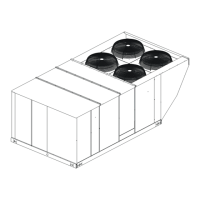
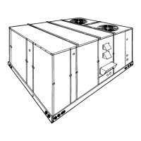
Overview of YORK Model DHG single package air conditioners with gas heat for outdoor installation.
Guidance on inspecting the unit for damage during transit and reporting any issues.
List of forms providing additional information on installation, operation, and service.
Details on design certifications by CGA and UL listing for the unit's intended use.
Explanation of the model coding system for YORK Sunline Ultra Gas/Electric units.
Mandatory adherence to national and local safety codes for unit installation.
Guidelines for selecting an optimal outdoor location, considering air supply and building structure.
Instructions for safely lifting and moving the unit, emphasizing proper sling and spreader use.
Specifies minimum clearances needed around the unit for proper operation and servicing.
Guidance on designing and sizing ductwork according to ACCA standards and connecting it to the unit.
Information on filter types, installation, and the importance of keeping them clean.
Instructions for installing the condensate drain line, including trapping for proper drainage.
Identification of removable panels providing access to internal unit components for service.
Recommendations for thermostat location and wiring for optimal performance and accuracy.
Details on field wiring requirements, grounding, and electrical code compliance.
Instructions for releasing compressor mounting bolts after unit installation.
Steps for removing and preparing hood components, filters, and sensors for installation.
Instructions for mounting the outdoor air sensor and connecting its wiring to the unit.
Procedure for assembling hood side plates, top cover, and ensuring proper corner sealing.
Steps for installing the fillpiece and filters into the hood assembly, noting airflow direction.
Guide for installing the provided bracket for mounting a field-supplied disconnect switch.
Information on the availability and installation of field-installed electric heater accessories.
Diagrams showing unit base with rails and considerations for bottom duct openings.
Detailed clearance requirements for front, back, left, right, and below the unit.
Information on electrical knockout hole sizes and their designated uses for wiring entry.
Instructions for managing duct covers for side and bottom duct applications.
Diagram illustrating the basic power wiring connections to the unit.
Wiring schematic for connecting a 24-volt thermostat to a cooling-only unit.
Wiring schematics for 24-volt and electronic programmable thermostats for cooling/heating.
Overview of the air-cooled condenser and the factory-charged refrigerant system.
Procedure for energizing the crankcase heater and performing initial unit warm-up cycles.
Detailed steps for single-stage and two-stage cooling operation based on thermostat input.
Explanation of safety controls like Freezestat, High Pressure Cutout, and Low Pressure Switch.
Description of the heating sequence for single-stage and two-stage heating thermostats.
Steps for controlling two-stage heating, including blower operation and first-stage heat.
Method for achieving continuous blower operation by adjusting thermostat wiring.
Importance of correct heat anticipator settings for temperature control and cycle length.
Procedure for measuring and balancing supply air CFM using static resistance and blower data.
Instructions for adjusting the variable pitch pulley on belt-drive blowers to achieve desired CFM.
Routine maintenance tasks including filter inspection, motor care, and outdoor coil cleaning.
Steps to ensure the owner understands unit operation, controls, and basic functions.