Do you have a question about the York YCUL0020 and is the answer not in the manual?
Explains the meaning of safety symbols used in the document to alert readers to specific situations.
Explains hazard terms and the manual's content, intended audience, and provides safety precautions.
Lists technical revisions made to the document, excluding formatting or grammatical changes.
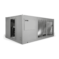
Provides an overview of the YCUL condensing units, their purpose, and construction details.
Details the hermetic scroll compressors used, including their design and features.
Describes the construction and specifications of the condenser coils.
Details the low noise airfoil section design of the composite fan blades.
Describes the totally enclosed air-over fan motors, their features, and bearings.
Outlines the components and connections within the unit's refrigerant circuit.
Explains the warranty coverage, limitations, and conditions for claims.
Lists the ISO accreditation and applicable industry standards and codes the units comply with.
Defines the primary responsibilities of individuals operating or working on the machinery.
Warns against using the unit for unintended purposes or outside specified design parameters.
Describes the YORK Air-Cooled Scroll Condensing Units, their application, and design.
Provides an overview of the unit's components and overall system description.
Details the hermetic scroll compressors used, including their design and features.
Describes the construction and specifications of the condenser coils.
Details the low noise airfoil section design of the composite fan blades.
Explains the display capabilities and printing functions for system information.
Describes how to enter setpoints or modify system values.
Lists the parameters that can be updated via the entry function.
Details standard and optional compressor power connection methods.
Describes the standard single-point terminal block connection for YCUL models.
Details the unit-mounted disconnect switch for power isolation during servicing.
Describes the unit-mounted circuit breaker for power isolation during servicing.
Explains the function and capacity of the control transformer.
Describes the factory-mounted capacitors for power factor correction.
Describes the factory-mounted accessory for operation in low ambient temperatures down to 0°F.
Describes the factory-mounted kit required for operation above 110°F ambient temperatures.
Details the interface options for connecting to building automation systems.
Lists available languages for unit controls and keypad display.
Describes the optional pressure transducers for sensing and displaying discharge pressure.
Describes the factory-mounted relief valves meeting Chicago code requirements.
Notes that service isolation valves are standard to the unit.
Explains the hot gas bypass feature for stable operation at low capacities.
Describes epoxy coated aluminum fins for corrosion resistance in specific environments.
Describes dipped-cured condenser coils suitable for most corrosive applications.
Describes coils with copbeforefins, not recommended for acid rain exposure.
Describes tamperproof enclosure panels that prevent unauthorized access.
Describes louvered panels that provide airflow while screening components.
Describes the individually enclosed compressor acoustic sound blanket.
Details the structure of the basic model number and its components.
Describes the Power Factor Capacitor feature and its options.
Details the Ambient Kits options for low and high ambient conditions.
Explains the BAS Reset/Offset options for system control.
Lists the available language options for the LCD and keypad display.
Describes the Readout Kits options, including standard and special pressure readouts.
Specifies the Safety Codes option for North American safety compliance.
Refers to sensor options and special quotes.
Describes the Motor Current Module option and special quotes.
Details the Remote Panel options, including OptiView and special quotes.
Explains the Sequence Kit options for unit control.
Describes Suction Temp options and special LWT requirements.
Lists options for Chicago code kits and service isolation valves.
Refers to standard and special optional valves.
Details the Hot Gas Bypass options for one or two circuits.
Refers to gauge options and special quotes.
Refers to overload options and special quotes.
Describes the Crankcase Heater option, standard or special.
Refers to DWP options and special quotes.
Refers to Insulation options and special quotes.
Refers to Flanges options and special quotes.
Describes the Flow Switch option and special quotes.
Refers to Vessel Codes options and special quotes.
Refers to Cooler options and special quotes.
Refers to PIN 44 options and special quotes.
Details the different types of condenser coils available, including aluminum and coated options.
Refers to PIN 46 options and special quotes.
Describes the Fan Motors options, including TEAO and special requirements.
Details the Enclosure Panels options, including wire and louvered types.
Describes the Acoustic Blanket options for noise reduction.
Refers to SR Documents options and special quotes.
Refers to PIN 51 options and special quotes.
Describes the Sound Fans options, including standard and ultra low sound.
Refers to paint options and special quotes.
Details the Vibration Isolators options: standard, seismic, neoprene, and special.
Refers to warranty options, noted as marketing purposes only.
Refers to Refrigerant Wty options, noted as marketing purposes only.
Describes Ship Instructions options, including Buy American Act compliance.
Refers to PIN 58 option, noted as marketing purposes only.
Refers to Pump package options and special quotes.
Refers to Pump Package Options and special quotes.
Indicates the Plant of Manufacture location.
Lists manufacturing locations like Monterrey and San Antonio.
Refers to YorkWorks version and upload options.
Refers to special quote options.
Details unit testing, shipping, and precautions for storing the unit before installation.
Instructs on inspecting the unit for shipping damage upon receipt and reporting any issues.
Lists essential checks to be performed before placing the units into operation.
Advises on careful handling of completely assembled units to prevent damage.
Specifies requirements for unit placement, including minimum clearances for airflow and servicing.
Details requirements for a flat, level foundation capable of supporting the unit's operating weight.
Provides recommendations for substantial, non-settling bases and security measures for ground locations.
Covers considerations for rooftop installations, emphasizing structural strength and roof protection.
Advises on siting the unit away from noise-sensitive areas and utilizing noise level data.
Offers ductwork recommendations for unit operation and performance.
Provides general guidelines for connecting refrigerant piping, emphasizing efficiency and design responsibility.
Recommends ASTM B280 material and provides derate information for R-410A systems.
Details maximum design working pressure and discharge pipe diameter for YCUL chillers.
Lists operating limitations, including voltage and temperature constraints, to prevent compressor damage.
Specifies absolute voltage limitations that must not be exceeded to prevent compressor damage.
Details the power supply requirements for the micro panel, including control power and overcurrent protection.
Lists the minimum and maximum voltage limits for different unit power configurations.
Control wiring diagram for low sound models.
Control wiring diagram for ultra low sound models.
Control wiring diagram for ultra low sound models across different voltages.
Control wiring diagram for low sound models.
Control wiring diagram for ultra low sound models.
Control wiring diagram for low sound models.
Control wiring diagram for ultra low sound models across various voltages.
Power connection diagram for low sound models across multiple voltages.
Power connection diagram for low sound models operating on 380-415 V/3/50 Hz.
Power wiring diagram for low sound models.
Power wiring diagram for ultra low sound models.
Power wiring diagram for ultra low sound models across various voltages.
Power wiring diagram for low sound models.
Power wiring diagram for ultra low sound models.
Power wiring diagram for low sound models.
Power wiring diagram for ultra low sound models across various voltages.
Connection wiring diagram for low sound models across multiple voltages.
Connection wiring diagram for low sound models operating on 380-415 V/3/50 Hz.
Connection wiring diagram for low sound models.
Connection wiring diagram for ultra low sound models.
Connection wiring diagram for ultra low sound models across various voltages.
Connection wiring diagram for low sound models.
Connection wiring diagram for ultra low sound models.
Connection wiring diagram for low sound models.
Connection wiring diagram for ultra low sound models across various voltages.
Lists isolator models with their rated capacity, deflection, and color codes.
Emphasizes that commissioning must be performed by authorized personnel familiar with the literature.
Lists basic checks to be performed with the unit's power switched OFF before commissioning.
Provides instructions for adding oil to the compressor circuit and checking oil levels.
Instructs to check fans for free rotation, damage, and secure guards.
Verifies electrical supply is from a single point and recommended fuse sizes are not exceeded.
Ensures the control panel is free of foreign materials and is clean.
Checks correct power cable connections to terminal blocks or circuit breakers.
Ensures the unit switch is OFF and circuit breaker is ON, verifying panel display illumination.
Verifies compressor heaters are energized and outlines pre-heating requirements based on ambient temperature.
Checks the correct fitting and wiring of the air flow switch into the control panel.
Covers initial checks before starting the unit, including inspection and refrigerant piping.
Details checks for shipping damage, piping, leaks, valve positions, oil level, and airflow.
Confirms compressor heaters are energized and checks voltage supply.
Covers panel checks, power verification, programming setpoints, and cycling components.
Ensures panel is clean, power is verified, and setpoints are programmed.
Explains how to program cooling setpoints and ranges for Discharge Air or Suction Pressure control.
Introduces the Millenium MicroComputer Control Center and its four main components.
Describes the microprocessor board's role as controller, input multiplexer, and output issuer.
Describes how the display shows unit status like running, demand, faults, and external cycling.
Lists general status messages that apply to individual systems or the entire unit.
Indicates the number of compressors running in System 1.
Indicates zone thermostats for System 1 are open.
Shows remaining time on the anti-recycle timer for System 1.
Indicates the anti-coincidence timer status for System 1.
Indicates when discharge pressure limiting is active, affecting system loading.
Indicates when suction pressure limiting is active, affecting system loading.
Shows that load limiting is in effect and the percentage of limiting applied.
Indicates Manual Override mode is selected, ignoring the daily schedule.
Indicates a compressor is in the process of pumping the system down.
Indicates a high discharge pressure cutout fault condition.
Indicates a low suction pressure cutout fault, protecting against coil freeze-up.
Indicates a Motor Protector or High Pressure Cutout fault.
Safety shutdown to protect the unit from operating in low ambient conditions.
Safety ensuring the system is not operated at voltages that could cause microprocessor malfunction.
Indicates the unit will shut down when voltage exceeds programmed trip voltage.
Indicates system shutdown if actual feedback voltage exceeds programmed trip voltage.
Safety shutdown for low ambient temperature, protecting the unit.
Safety preventing operation at damaging low voltages affecting the microprocessor.
Indicates unit shutdown due to exceeding programmed trip voltage related to current.
Warns of low battery, indicating loss of programmed values and prevention of unit operation.
Indicates an incorrect unit type configuration, requiring a jumper for proper operation.
Lists general status messages like Unit Switch Off, Remote Shutdown, and Daily Schedule Shutdown.
Lists system safeties such as high discharge pressure and low suction pressure faults.
Lists unit safeties including low ambient temperature and 115VAC undervoltage.
Lists unit warnings such as Low Battery and Incorrect Unit Type.
Describes how to access unit and system operating parameters using the OBeforeData key.
Describes how to obtain a printout of current system operating parameters.
Allows selection of history buffers to view shutdown conditions.
Shows the date and time when a specific shutdown occurred.
Displays the unit's software version.
Indicates the type of fault that occurred, specifically low suction pressure.
Displays the unit type, confirming it as a condensing unit.
Shows the type of ambient control, standard or low.
Indicates the current control mode selection: local or remote.
Indicates the control mode is suction pressure.
Shows the lead/lag control type: manual or automatic.
Indicates the fan control mode is based on discharge pressure.
Shows whether manual override mode is enabled or disabled.
Displays the type of current feedback utilized.
Indicates if the optional European Soft Start was installed.
Displays the programmed discharge pressure cutout setting.
Displays the programmed suction pressure cutout setting.
Describes how arrow keys are used with other keys for scrolling and changing values.
Details how to program cooling setpoints and ranges for different control modes.
Offers a quick reference list for information available under the OBeforeDATA key.
Describes how to scroll through and change programmable options using the OPTIONS key.
Allows programming of the display language to English, Spanish, French, German, or Italian.
Explains the system switches for controlling individual systems and the effect of turning them OFF.
Describes ambient control types: Standard (25°F cutout) and Low Ambient (0°F cutout) with kit requirement.
Initiates the unit start sequence, detailing the role of permissive inputs and evaporator blower contacts.
Explains anticipatory controls to prevent low-pressure cutouts, detailing loading prevention based on suction pressure.
Describes controls that unload the system before safety limits are reached due to high load.
Details the setpoint, high/low limits, and sequences for controlling discharge air temperature.
Details low ambient condenser fan control logic based on discharge pressure.
Details low ambient condenser fan control logic based on discharge pressure.
Explains how to clear history buffers, with a warning about potential data loss.
Describes Service Mode for enabling/disabling outputs and viewing inputs/configuration.
Details how to view and modify unit configuration and operating parameters in Service Mode.
Emphasizes the critical need to correctly program these settings to prevent compressor damage.
Lists I/O digital input connections and their descriptions.
Lists I/O digital output connections and their descriptions.
Lists I/O analog input connections and their descriptions.
Lists I/O analog output connections and their descriptions.
Details connections and voltage readings for the outside air sensor.
Provides correlation between outdoor air temperature and voltage signal input.
Provides correlation between discharge air temperature and voltage/resistance.
Lists required parts for printer installation, including the printer and cable components.
Details component assembly and wiring as shown in Figure 45.
Explains how to obtain a printout by pressing the PRINT key and then OBeforeDATA or HISTORY.
Troubleshooting steps for issues related to no display or unit not operating.
Troubleshooting steps for flow switch or remote stop no-run permissive faults.
Troubleshooting steps for low suction pressure faults, covering adjustments, charge, and components.
Troubleshooting steps for high discharge pressure faults, including fan operation and refrigerant issues.
States owner responsibility for maintenance and warns about warranty voidance due to lack of it.
Provides guidance on checking oil level, oil analysis, and critical warnings regarding compressor operation.
States that condenser fan motors are permanently lubricated and require no maintenance.
Advises on keeping condenser coil surfaces clean and exercising care during cleaning.
Recommends regular checks of system operating parameters against limitations.
Explains the function of the Real Time Clock chip and its battery backup for retaining setpoints.
Recommends periodic inspections for loose hardware, component operation, and refrigerant leaks.
Explains how data can be read/modified via serial communication and lists parameters.
Data that can be read and modified via BACnet or Modbus, including Modbus Register Addresses.
Data that can be read and modified via BACnet or Modbus, including Modbus Register Addresses.
Data readable via BACnet/Modbus but not modifiable, including Modbus Register Addresses.
Data readable via BACnet/Modbus but not modifiable, including Modbus Register Addresses.
Details the 8 data values received from MicroGateway/E-Link for control parameters in REMOTE mode.
Explains how the unit transmits operational or history data based on 'History Buffer Request'.