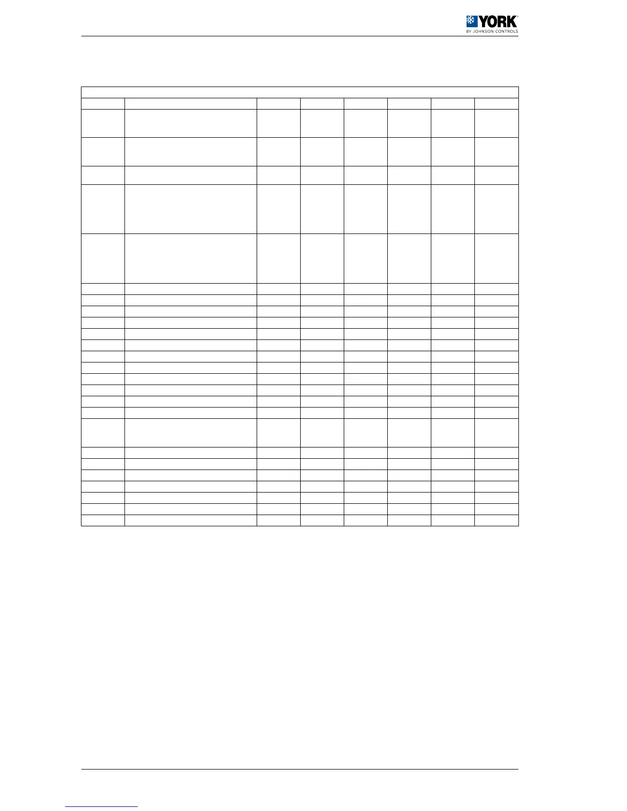
1.2.4 Parameters relating to sensors
Parameters relating to sensors
Display Description Level VS Unit Max. Min. Value
/01
NTC B1 sensor (water inlet):
0= Absent (function not available
1= Present
F 1 (R/W) - 1 0 1
/02
NTC B2 sensor (water outlet):
0= Absent (function not available)
1= Present
F 2 (R/W) - 1 0 1
/03
NTC B3 sensor (Outdoor temperature):
0= Absent
F 14 (R/W) - 1 0 2
/04
B4 sensor:
0= Absent
1= ON/OFF
2= NTC
3= Ratiometric 5 Vdc
F 15 (R/W) - 3 0 3
/08
B8-type sensor:
0= Absent
1= ON/OFF
2= NTC
3= Ratiometric 5 Vdc
F - 3 0 3
/09 Minimum input voltage F 18 (R/W) 0.01 Vdc /10 0 50
/10 Maximum input voltage F 19 (R/W) 0.01 Vdc 500 /09 450
/11 Minimum pressure F 1 (R/W) bar /12 0 0
/12 Maximum pressure F 2 (R/W) bar 99,9 /11 45
/13 B1 sensor calibration F 3 (R/W) °C 12 -12 0
/14 B2 sensor calibration F 4 (R/W) °C 12 -12 0
/15 B3 sensor calibration F 5 (R/W) °C 12 -12 0
/16 B4 sensor calibration (accessory) F 6 (R/W) bar 12 -12 0
/19 B7 sensor calibration F °C 12 -12 0
/20 B8 sensor calibration (accessory) F bar 12 -12 0
/21 Digital filter U 20 (R/W) - 15 1 4
/22 Input limitation U 21 (R/W) - 15 1 8
/23
Measuring unit
0=C
1=1F
U 5 (R/W) - 1 0 0
b00 Sensor viewed on display U 24 (R/W) - 7 0 0
b01 Value read by sensor B1 D 70 (R) °C - - -
b02 Value read by sensor B2 D 71 (R) °C - - -
b03 Value read by sensor B3 D 72 (R) °C - - -
b04 Value read by sensor B4 D 73 (R) bar - - -
b07 Value read by sensor B7 D 76 (R) °C - - -
b08 Value read by sensor B8 D 77 (R) bar - - -
1 User manual
1.2 Operating instructions µC2 (YLHA 50, 60 and 80)
12

 Loading...