Do you have a question about the York ZF076 and is the answer not in the manual?
| Brand | York |
|---|---|
| Model | ZF076 |
| Category | Air Conditioner |
| Language | English |
Discusses safety alert symbols and signal words (DANGER, WARNING, CAUTION) for injury prevention.
Details procedures for inspecting the unit for transit damage upon receipt.
Warns about fire/explosion hazards from improper handling of flammable liquids and gas leaks.
Emphasizes strict compliance with installation instructions and codes for safe operation.
Lists additional information sources for design, installation, operation, and service.
Information on obtaining authorized replacement parts from local distributors.
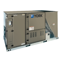
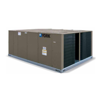
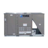
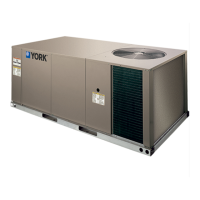
Lists approved uses and installation types for the unit.
Highlights the requirement for installation to comply with all applicable codes and regulations.
Warns that improper installation can lead to personal injury or property damage.
Notes the system uses R-410A refrigerant, which operates at higher pressures than R-22.
Read instructions before installation; ensure they are available to the consumer.
Outlines installation requirements based on national and local codes and standards.
Provides guidelines for selecting a suitable outdoor installation location for the units.
Details required clearances for proper unit operation and service access.
Details filter types, installation, and maintenance requirements.
Identifies removable panels providing access to serviceable components.
Illustrates typical field power wiring connections for single and three-phase supplies.
Shows typical control wiring connections between the thermostat and the unit control board.
Provides guidelines for locating and installing the room thermostat.
Outlines requirements for field wiring, grounding, and voltage tolerances.
Describes gas-fired heaters, their heat exchangers, and ignition systems.
Covers proper sizing of gas piping based on flow rate, gravity, and run length.
Details routing of the gas supply line through unit knockouts.
Provides recommendations for gas piping installation, including drip legs and unions.
Discusses field conversion for LP/propane gas and associated equipment requirements.
Refers to instructions for field assembly of an economizer rain hood.
Refers to instructions for field assembly of power exhaust/barometric relief damper.
Describes the components of the economizer user interface (LCD and keypad).
Details the function of the navigation buttons for the economizer keypad.
Provides instructions on navigating menus using the keypad buttons.
Lists the top-level menus available on the economizer controller.
Explains that parameters are conditional based on sensor presence and function enablement.
Discusses economizer sequences driven by Smart Equipment™ controls.
Describes setting the economizer minimum position during occupied mode.
Details the conditions for free cooling using dry bulb temperature comparison.
Details conditions for free cooling using single enthalpy comparison.
Details conditions for free cooling using dual enthalpy comparison.
Describes how the control determines free cooling type based on available sensors.
Explains how free cooling is implemented, including damper modulation and compressor engagement.
How thermostat inputs affect free cooling operation and compressor use.
Discusses sensor inputs and their role in controlling supply air temperature during free cooling.
Lists adjustable parameters for the power exhaust system.
Describes the electrical outputs used to control external fans and actuators.
Explains how the power exhaust system operates in conjunction with the economizer.
Explains the function of indoor air quality sensors and their effect on actuator modulation.
Provides an overview of the Jade Economizer interface for Simplicity Lite controls.
Describes the components of the Jade Economizer user interface (LCD and keypad).
Details the function of the navigation buttons for the Jade Economizer.
Instructions for navigating menus using the keypad.
How to use the keypad for settings, system setup, advanced settings, and alarms.
Lists the order of menus displayed on the economizer module.
Explains the initial setup and configuration process for the JADE™ Economizer module.
Describes the LCD screen saver behavior when the unit is inactive.
Discusses proper compressor rotation and how to correct misphased electrical connections.
Describes the types of supply air blowers used and their adjustment methods.
Explains how to determine the supply air blower speed based on performance data.
Warns that belt drive blower systems require adjustment for specific static and CFM requirements.
Step-by-step guide for adjusting belt tension on blower systems.
Warns about potential blower damage from improper system air quantity adjustment.
Explains how the unit operates during cooling calls, including blower and compressor sequences.
Describes how to set the fan switch to "ON" for continuous blower operation.
Explains operation when the fan switch is set to "AUTO".
Describes the cooling operation sequence when no outdoor air options are present.
Details cooling operation with economizer using single enthalpy or dry bulb sensors.
Describes economizer operation using dual enthalpy sensors for optimal efficiency.
Explains how power exhaust integrates with economizer operation.
Describes the operation of motorized outdoor air dampers.
Outlines how the system handles cooling operation errors and safety shutdowns.
Describes the function and behavior of the high-pressure limit switch during cooling.
Explains the monitoring and response to the low-pressure limit switch during cooling.
Details how the freezestat protects the system and initiates shutdown.
Describes the evaporator low limit sensor's function and shutdown procedures.
Explains low ambient cooling mode operation for Simplicity Lite systems.
Explains low ambient cooling mode operation for Smart Equipment™ systems.
Lists safety controls monitored by the unit control board for cooling systems.
Details inherent compressor protection features like anti-short cycle delay.
Explains how the unit displays error codes or messages for troubleshooting.
How to reset pressure or freezestat lockouts by adjusting the thermostat.
Describes the operational sequence for electric heating.
Explains the sequence for single-stage electric heating operation.
Explains the sequence for two-stage electric heating operation.
Lists safety controls included in the electric heat control circuit.
Explains how the UCB initiates flash codes for system errors.
How to reset flash codes by adjusting the thermostat setting.
Discusses the importance of correct anticipator setpoints for heat cycles.
Details the sequence of operation for gas heating.
Describes two-stage furnace operation with single or two-stage thermostats.
Explains how the ICB monitors gas heat operation and handles errors.
Describes the location and function of temperature limits in the furnace.
Explains how the UCB monitors the gas valve and handles faults.
Details the function and troubleshooting of the centrifugal switch.
Explains the purpose and troubleshooting of the rollout switch.
Describes the flame sense circuit's role and failure indications.
Explains how the UCB initiates flash codes for system errors.
Discusses the importance of correct anticipator setpoints for heat cycles.
Provides instructions for starting up the cooling system.
Lists checks to perform after installation but before starting the unit.
Steps to follow for operating the unit in cooling mode.
Instructions for safely lighting the pilot and main burners on gas heat units.
Procedures for safely shutting down the unit.
Checks to perform after the gas heating section has started operation.
Warns about fire/explosion hazards from improper testing of gas connections with open flames.
Steps for checking and adjusting the pilot flame for proper operation.
Procedures for checking or changing burners, pilots, or orifices.
How to adjust the high-fire gas flow by turning the pressure regulator screw.
Instructions for adjusting burner shutters to prevent yellow flame.
Procedures for checking the gas input rate to the furnace.
Step-by-step guide for troubleshooting cooling system issues.
Step-by-step guide for troubleshooting gas heating system issues.
Emphasizes caution when working with live electrical components during troubleshooting.
Advises labeling wires before disconnection to prevent wiring errors and dangerous operation.
Warns that the furnace may shut down on high temperature during troubleshooting procedures.
Guides on how to interpret and troubleshoot flash codes.
Troubleshooting procedures for the ignition control board and its components.
Troubleshooting steps for issues related to the centrifugal switch.
Explains pilot flame lockout conditions and troubleshooting steps.
Discusses temperature limits and their role in furnace operation and safety.
Troubleshooting steps for issues related to the rollout switch.
Troubleshooting steps for when a flame is present without a call for heat.
Troubleshooting for gas valve operational issues.
Troubleshooting steps for flame sense circuit failures.
Explains the various flash codes used by the control boards for troubleshooting.
Describes how to field adjust fan ON and OFF delays.
Lists components needed to access Smart Equipment™ control points.
Details limit, power, and shutdown connections on the UCB.
Details thermostat connection terminals on the UCB.
Explains the status indicated by the LEDs on the UCB.
Describes space temperature sensor connections on the UCB.
Details pin temperature sensor connections on the UCB.
Lists pinned connections on the right edge of the UCB.
Details terminals at the lower right corner of the UCB.
Describes heat section connection pins on the UCB.
Details cooling and fan output connections on the UCB.
Explains refrigerant circuit safety switch and blower overload connections on the UCB.
Details SA BUS connections on the UCB.
Lists components of the integrated user interface on the UCB.
Describes the USB connector on the UCB for data transfer.
Details FC BUS connections on the communication board.
Describes the EOL selector switch on the communication board.
Explains the LEDs on the communication board.
Shows the wiring diagram for the Simplicity Lite control board.
A checklist covering common startup procedures and points for package equipment.
Outlines the warranty policy for Johnson Controls/Ducted Systems equipment.
Instructions on using the local LCD or Mobile Access Portal for equipment startup.
Critical safety warnings regarding lethal voltages and moving parts during startup.
Section to record design application data like CFM and static pressures.
Checklist for inspecting the unit for shipping, installation, and general condition.
Inspection points related to the blower system, including alignment and tension.
Checklist for inspecting the exhaust fan and related components.
Checklist for inspecting economizer operation and settings.
Section to record electrical measurements like voltage and amperage for various components.
Checks related to refrigerant circuit safety controls and compressor rotation.
Lists measurements to record for gas heating operation, including gas pressure and temperature rise.
Steps to verify correct staging of heating and cooling stages.
Steps to verify the variable frequency drive's modulation with duct pressure.
Final inspection steps, including set point verification and panel closure.