Do you have a question about the YORKVILLE PS10P and is the answer not in the manual?
Covers essential safety guidelines, risk of electric shock, fire hazards, and proper usage.
Details on connecting power, using extension cords, and protecting the power cord.
Instructions on proper ventilation, avoiding water, and when to seek qualified service.
Adherence to UL60065 standards for product safety and operation.
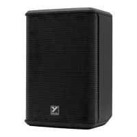
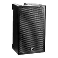
Visual guide identifying key components on the speaker enclosure.
Comprehensive lists of parts for PS10P, PS12P, and PS15P models.
Detailed component listing for M1525 models.
Detailed component listing for M1523 models.
Schematic detailing the low voltage power supply section of the PS Preamp.
Schematic for adjusting signal gain for line level inputs.
Schematic for adjusting signal gain for microphone level inputs.
Diagrams for Bass Boost and Mixer Enable input control circuits.
Schematic for the main volume control stage.
Top and bottom views showing component placement on the M1523 circuit board.
Record of design changes and updates made to the M1523 model.
Listings of potentiometers used, their part numbers, and styles.
Schematic of the power regulation circuit for the woofer amplifier.
Schematic for the negative gain stage in the woofer amplifier.
Schematic for the positive gain stage in the woofer amplifier.
Schematic detailing the signal path and components of the horn amplifier.
Schematic for the auxiliary power supply section of the PS 10P.
Diagrams showing the physical placement of components on the PS10P circuit board.
Diagram illustrating component placement on the underside of the M1525 board.
Specific notes for assembling the PS10P board, including component placement.
Guidelines for securing components using RTV and tie wraps.
Illustrations showing the pin configurations for specific transistors.
Log of design changes and revisions for the M1525 PCB.
Schematic of the power regulation circuit for the woofer amplifier.
Schematic for the negative gain stage of the woofer amplifier.
Schematic for the positive gain stage of the woofer amplifier.
Schematic detailing the horn amplifier's components and signal flow.
Schematic illustrating the auxiliary power supply section.
Diagrams showing component layout on the M1520 V04 PS12P/15P board.
Specific instructions for assembling and handling PS12P/PS15P boards.
Guidance on RTV usage and securing components like coils and transistors.
Record of design changes and revisions for the M1520 PCB.
Illustrations showing pin configurations for 35N60CFD and IRFB4227 transistors.
| Active or Passive | Active |
|---|---|
| Biampable | No |
| Maximum SPL | 126dB |
| Type | 2-way |
| Power Output | 500 Watts |
| Max SPL (dB) | 126dB |
| Frequency Response | 55Hz - 18 kHz |
| LF Driver(s) | 10 inch |
| Woofer | 10 inch |
| Inputs | XLR, 1/4" |
| Outputs | XLR |
| Mixer Controls | EQ |
| Amplifier Power | 500 Watts |
| HF Driver(s) | 1.4" Compression Driver |
| Tweeter | 1.4" Compression Driver |
| HF Dispersion (°H x °V) | 90° x 60° |
| Weight | 34 lbs (15.4 kg) |
| Dimensions | 19.5" x 12.2" x 11.8" (495 x 310 x 300 mm) |