EasyManua.ls Logo

YORKVILLE PSA1s User Manual

YORKVILLE PSA1s
34 pages
To Next Page IconTo Next Page
Page #1 background imageLoading...
Page #1 background image
SERVICE MANUAL
PSA1S
REV1 + REV2
SMT Disclaimer
Due to the complex nature of the use of SMT installed components
in Yorkville equipment, we highly caution all service technicians in
attempting to repair or replace SMT factory installed components.
Many of these components may be glued prior to initial soldering.
Replacing SMT components requires expensive
specialized de-soldering equipment and training.
Yorkville Sound will repair and replace defective SMT components
to ensure proper quality assurance and installation is maintained.
U.S.A.
Yorkville Sound Inc.
4625 Witmer Industrial Estate
Niagara Falls, New York
14305, USA
Voice: 716-297-2920
Fax: 716-297-3689
WORLD HEADQUARTERS
CANADA
Yorkville Sound Limited
550 Granite Court
Pickering, Ontario
L1W 3Y8 CANADA
Voice: 905-837-8481
Fax: 905-837-8746
Manual-Service-PSA1S-00-2v0 ƒ November 7, 2018
Question and Answer IconNeed help?

Do you have a question about the YORKVILLE PSA1s and is the answer not in the manual?

YORKVILLE PSA1s Specifications

General IconGeneral
Active or PassiveActive
LimiterYes
LF Driver(s)15"
InputsXLR, 1/4"
OutputsXLR
Enclosure ConstructionBirch Plywood
Frequency Response (Hz)40Hz - 150Hz
Input Sensitivity (Vrms Sine)1.4 Vrms

Summary

Product Overview and Company Information

SMT Component Disclaimer

Caution regarding repair of SMT components due to complexity and specialized equipment.

Rear Panel Interface

Power Controls and Indicators

Controls for power, circuit breaker, and status indicators.

Input and Level Controls

Connectors and adjustments for audio input and output level.

Technical Specifications

Performance Characteristics

Detailed electrical and acoustic performance specifications of the PSA1S.

Physical and Construction Details

Dimensions, materials, and finish specifications.

System Block Diagram

Signal Flow Overview

Visual representation of the signal flow through the PSA1S amplifier.

Bill of Materials

Component Identification

Comprehensive lists of components used in the PSA1S, by reference designator.

Preamp Circuit Schematics

Preamp Signal Processing

Schematic detailing the preamp's signal path, including limiter and boost.

MCU and Power Supply Schematics

Power Supply Circuitry

Schematic of the power supply, detailing its components and connections.

Microcontroller and Protection Circuits

Schematic for the microcontroller and associated protection circuits.

PCB Information and Component References

PCB Revision History

Log of design changes and version updates for the M1449 PCB.

Potentiometers and Knob Details

List and diagrams of potentiometers and knobs used for controls.

Integrated Circuit Pinout Reference

Pinout diagrams for key ICs used in the PSA1S.

A-1014 Amplifier Module Pinout

Amplifier Module Pin Definitions

Detailed pinout and function description for the A-1014 amplifier.

M1449 PCB Layout Diagram

Component Placement Overview

Diagram showing the physical placement of components on the M1449 PCB.

Production and Assembly Notes

RTV Application and Mounting Procedures

Instructions for applying RTV sealant and mounting hardware.

Power Supply Schematic Details

AC Input and Transformer Connections

Schematic details of AC input, filtering, and transformer connections.

DC Output and Voltage Regulation

Schematic of DC output voltages and regulation circuits.

Subwoofer Amplifier Schematic Details

Input Stage and Signal Processing

Schematic of the subwoofer amp's input stage and signal processing.

Output Stage and Protection Circuits

Schematic of the output stage, protection, and silent ON/OFF.

M1694 PCB Layout Diagram

Component Placement Details

Diagram showing component placement on the M1694 PCB.

PCB Assembly Documentation and RTV Instructions

Mounting Hardware and Procedures

Instructions for mounting heat spreaders, components, and RTV application.

PSA1S-M1698V02 Schematic

Signal Path and Component Layout

Schematic showing signal path and component layout for the M1698V02.

Product Identification and Parts

External Component Identification

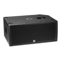
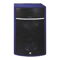
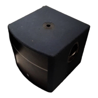
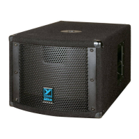
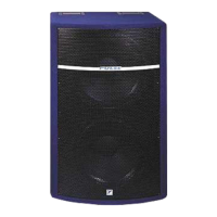
Image identifying key external components and their labels.

Included Parts and Accessories

List and quantity of included parts and accessories.

Eyebolt Installation and Safety

Safety Precautions and Tool Requirements

Critical safety warnings and required tools for eyebolt installation.

Eyebolt Installation Procedure

Step-by-step guide for installing eyebolts for suspension.

Working Load Limit Specifications

Specifications for safe working load limits of the enclosures.

Service Bulletin: Limiter Update

Disassembly for Modification

Instructions for safely disassembling the PSA1s to access internal components.

Limiter Update Procedure

Internal Modification and Re-assembly

Steps for performing the limiter update and reassembling the unit.

Related product manuals