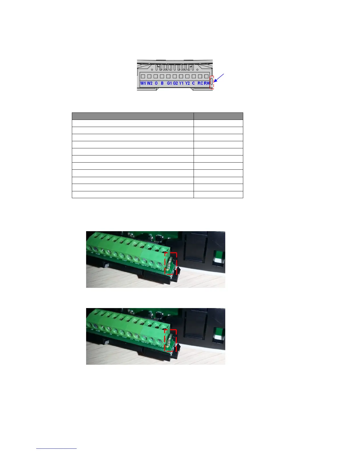
EasyManua.ls Logo

Z-Wave ZTS-500 - Thermostat Terminal Wiring; RC;RH Jumper Configuration

Z-Wave ZTS-500
34 pages
Print Icon
To Next Page IconTo Next Page
To Previous Page IconTo Previous Page
Loading...
7
Thermostat Terminal Wiring
Figure 6. Terminal block and pin assignment
Terminals
Symbol
1
st
s
tage
H
eater
W1
or W
2
nd
s
tage
H
eater
W2
Cool c
hangeover
(heat pump)
O
Heat c
hangeover
(heat pump)
B
1
st
stage
Fan
G
1 or G
2
nd
stage
Fan
G2
1
st
stage
Compressor
Y
1 or Y
2
nd
stage
Compr
essor
Y
2
24Vac Common
C
24V
ac
Power for C
ooling
R
C
24V
ac
Power for H
eat
ing
R
H
RC/RH jumper:
Most HVAC systems build-in a common heating and cooling transformer. The ZTS-500
has a built-in RH/RC jumper wire to connect RH and RC inputs for this configuration.
If the HVAC system contains separated heating and cooling transformers, please cut out
the RH/RC jumper and then connect the RC and RH inputs individually.
Thermostat wiring:
For Non-Heat Pump HVAC systems, please refer to figure 7, 8, and 9.
For Heat Pump HVAC systems, please refer to figure 10, 11, and 12.
RC/RH jumper
RC/RH jumper
Cut out RC/RH jumper!

Related product manuals