※
The specifications of product may change without any prior notice to improve performance.
3
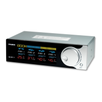
Graphic Power Load Meter: Displays power between 30 to 800W in 4 stages.
Numeric Power Load Display: Numerically displays power between 30 and 800W.
(The Numeric Power Load Display will read “LLL”when an overflow occurs. “LLL”indicates power
loads beyond the unit’s measurable range.)
Fan Status Display: The Fan’s operation status is indicated with animated propeller images.
Fan Channels
RPM Display: During RPM Setting, RPM is displayed in units of 60RPM, and actual operational RPM is
displayed in units of 10RPM.
Temperature Display: Displays temperature readings between -9
℃
and +99
℃
Jog Wheel: Used for adjusting Fan RPM. RPM can be set from 1000 to 5940RPM in units of 60RPM.
Mode Button: Used for selecting a Fan Channel and saving the Fan RPM setting.
Front Panel
Standard Fans (Fan 1~3): 3-Pin fans that include the RPM output function can be connected for use.
PWM Fan (Fan 4): 4-Pin fan that includes the PWM function can be connected for use.
Temperature Sensing: Four temperature sensors can be connected.
CVS Terminal: Receives the measured values of the CVS.
Power Connector: Connects with the PSU’s 4-Pin connector.
Back Panel
 Loading...