TEMPERATURE CONTROL CHARACTERISTICS
KEYBOARD LOCK STATUS
CONTROL IN THE MANUAL AND AUTOMATIC MODE
NOTES
If the temperature from the check sensor is equal or higher than the temperature setting, then the load connected to the terminals (2), (4) is switched off.
If the temperature from the check sensor is lower by 2°C than the temperature setting, then the load connected to the terminals (2), (4) is switched on.
The heating symbol on the display is active. The symbol comes off when the temperature in the room reaches the set value. When the sensor is set in
the MODE – “0” (F5 tab), and if the external sensor detects the increase of the temperature above the upper safety limit, then the heating is switched off.
At the OFF status the system switches the heating on when the temperature is lower than the safety temperature set in the F3 mode.
Notes: in the normal operation mode it is possible to set the temperature directly by pressing the “+” / “-” buttons. Pressing the “
” button for short time
or no action for 10 minutes makes the system leaving the temperature setting mode.
In the normal operation mode press simultaneously and hold the “+” and “-” buttons to enable/disable the keyboard lock. When the keyboard is locked
the system is not active and does not respond to pressing buttons, and the “Lock” is shown in the right hand upper corner of the LCD display.
In the normal operation mode press and hold for about 5 seconds the button “-” to switch between manual and automatic modes.
Manual mode: temperature adjustment in accordance with the set value only, without displaying the operation time range (P1÷P4).
Automatic mode: temperature adjustment in accordance with the set value for the current operation time range; the temperature within diverse
operation time ranges and various working days can be different – in accordance with the program set.
This symbol informs that the device creates an electric shock hazard when servicing
The system should be serviced by appropriately qualied electricians who has familiarized himself with the operating manual and the functions of the device.
In the normal operation mode press and hold for about 5 seconds the button “-” to switch between manual and automatic modes.
Manual mode: temperature adjustment in accordance with the set value only, without displaying the operation time range (P1÷P4).
Automatic mode: temperature adjustment in accordance with the set value for the current operation time range; the temperature within diverse
operation time ranges and various working days can be different – in accordance with the program set.
Note Description
After connecting the temperature controller to the power supply
230 VAC no signs on the display
Check the wiring and the connection of the temperature controller
with the mains – 230 VAC/50Hz
After pressing any button no backlight comes on Backlight system damaged
Temperature in the room is lower by 2 °C
than the temperature set,
and in spite of that the oor heating does not come on
Check the pad connection to the temperature controller.
Check the relay operation.
The system does not operate correctly Switch the power supply off and then switch it on again
The display shows wrong date and time
Caused by a power supply failure for more than 2 hours.
Recheck settings, make new correct ones.
The temperature controller executes
wrong timed operation program
Caused by a power supply failure for more than 2 hours.
Recheck settings, make new correct ones.
The controller does not execute the timed operation program
The controller set in manual mode.
Switch the controller over to automatic mode.
WARRANTY CARD
There is 24 months guarantee on the product
Salesman stamp and signature, date of sale
1. ZAMEL Sp. z o.o. assures 24 months guarantee for the product.
2. The manufacturer’s guarantee does not cover any of the following actions:
a) mechanical damage during transport, loading / unloading or under other circumstances,
b) damage caused by incorrect product mounting or misuse,
c) damage caused by unauthorised modications made by the PURCHASER or any third parties to the product or any other devices
needed for the product functioning,
d) damage caused by Act of God or any other incidents independent of the manufacturer - ZAMEL Sp z o.o.
e) power supply (batteries) to be equipped with a device in the moment of sale (if they appear);
3. The PURCHASER shall lay any claims in writing to the dealer or ZAMEL Sp. z o.o.
4. ZAMEL Sp. z o.o. is liable for processing any claim according to current Polish legislation.
5. ZAMEL Sp. z o.o. shall process the claim at its own discretion: product repair, replacement or money return.
6. The manufacturer’s guarantee is valid in the Republic of Poland.
7. The PURCHASER’s statutory rights in any applicable legislation whether against the retailer arising from the purchase contract or
otherwise are not affected by this warranty.
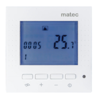
APPEARANCE
This device is to be connected to sin-
gle-phase mains, in accordance with the
s
tandards in force in the respective country.
Installation must be carried out according
to this instruction manual. The installation,
connection and adjustment of the device should be
carried out by a competent and appropriately qualied,
licensed electrician who has familiarized himself with
this instruction manual and the functions of the device.
Warning! Do not remove the casing! Electric shock risk!
Before installation, dismantling, cleaning, and servicing
disconnect power supply and make sure the terminals
are voltage-free. For installing use a straight blade
screwdriver of the diameter up to 3.5 mm. The correct
operation of the device is affected by its transportation,
storage, and use, and particularly how the temperature
controller and sensor have been installed. Installation
of this device is not recommended in the following situ
-
ations: the lack of parts, damage or deformations of the
d
evice. If the device does not operate properly, please
contact the manufacturer.
CAUTION
INSTALLATION
TECHNICAL SPECIFICATIONSDESCRIPTION
● Disconnect supply circuit by means of a fuse, an
overcurrent protection device or a switch discon-
nector connected to the appropriate circuit.
●
Check the voltage free status on supply connectors
using an appropriate tester.
● Install the RTP-01 device in a room, in accordance
with the instructions given in the “Description” para
-
graph.
●
Connect leads to the connecting terminals accord-
ing to the electrical diagram.
●
Switch on the power supply circuit.
● Check the operation of the controller and the instal
-
lation.
RTP-01 temperature controller is used to control
the electrical floor heating systems under load.
The device is installed in a deepened 60 mm
x 60 mm wiring box.
●
The controller is to be installed in a heated
room – installation in a deepened 60 mm x
60 wiring box at the height about 120 cm
above the heated floor level.
● The controller is to be installed in a safe
place, not exposed to direct sun light, in a
slightly airy area
● The temperature and humidity in the instal
-
lation place should not exceed the values
listed in the technical specification (T < -5
OR T > +50
°C, relative humidity RH > 90%)
RTP-01
Input (supply) terminals: L (5), N (6)
Input rated voltage: 85 ÷ 265 V~
Nominal frequency: 50 / 60 Hz
Nominal power consumption: 6 mA / 0.4 W (STANDBY)
Battery support: no
NTC sensor terminals: (6), (7)
NTC sensor terminals: NTC 5 k dla 25 ºC
Temperature adjustment range: +5 ÷ +45 °C
Accuracy of temperature measurement: ±1 °C
Control accuracy: 0 °C ÷ -2 °C
Output terminals: (2), (4)
Output type: 1NO-16 A / 250 V AC1 4000 VA voltage contact
Connection terminals quantity: 7
Section of connecting cable: 0,5 ÷ 2,5 mm
2
Ambient temperature range: -5 ÷ +50 °C
Humidity: <90%, no condensation
Installation: deepened wiring box 60 mm x 60 mm
Casing material: polycarbonate (PC)
Casing protection degree: IP40
Protection level: II
Overvoltage category: II
Dimensions: 86 x 86 x 45.5 mm (H x W x D)
Weight: 136 g
Reference standard: EN 60335-1:2002+A2:2006,
EN 61000-3-2:2006, EN 61000-3-3:2006,
EN 55014-1:2006+A1:2009,
EN 55014-2:1997+A2:2008
heating mat
controller
LCD display
LED
ON/OFF button
“–” button
“+” button
Menu button
NTC 5k sensor
N
Heating element
L, fuse, B- characteristics
(6A/10A, power dependent)
The symbol indicates the selective
collection of the electric and electronic
equipment. Do not dispose electrical
and electronic waste together with
another kind of waste.