MATEC – ELECTRIC HEATING SYSTEMS
TEMPERATURE CONTROLLER RTS-01A
INSTRUCTION MANUAL
ZAMEL Sp. z o.o.
ul. Zielona 27, 43-200 Pszczyna, Poland
tel. +48 32 449 15 00, +48 32 210 46 65, fax +48 (32) 210 80 04
www.zamel.com, e-mail: matec@zamel.pl
VER. 002_17.06.2016
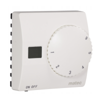
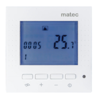
APPEARANCE
The device is designed for one-pha-
se installation and must be installed in
accordance with standards valid in a
particular country. The device should
be connected according to the details
included in this instruction manual. Installation,
connection and control should be carried out by a
qualied electrician staff, who acts in accordance
with the instruction manual and the device func
-
tions. Disassembling of the device is equal with a
loss of guarantee and can cause electric shock. Be
-
fore installation make sure the connection cables
are not under voltage. The cruciform head screw
-
driver 2,5 mm should be used to install the device.
Improper transport, storage, and use of the device
inuence its wrong functioning. It is not advisable
to install the device in the following cases: if any
device’s part is missing or the device is damaged
or deformed. In case of improper functioning of the
device contact the producer.
The symbol stands for selective
collection of electrical and electronic
devices. Placing used devices with
other waste is not allowed
CAUTION
FEATURES
TECHNICAL DATADESCRIPTION
● LCD display showing current room tempe-
rature
● Economical or comfort mode operation
● Optional temperature display: Celsius or
Fahrenheit scales
● Temperature controlled by built-in (internal)
sensor, or external oor sensor
● Easy to use
The RTS-01A temperature controller is
a non-programmable controller used for oor
heating. The controller cooperates with electric
oor heatig system. The RTS-01A device can
control the temperature by means of built-in
(internal) or oor (external) sensor.
The temperature controller should be instal-
led:
●in a heating room (at surface mounting, or
in cable box Ø60), 120 cm high from the he-
ating zone
● in a place not exposed to direct sunlight
● in a place not exposed to strong wind blows
The temperature in the mounting place should
be from 5°C to +50°C
RTS-01A
Input terminals: L (5), N (6)
Input rated voltage: 100 ÷ 240 V~
Nominal frequency: 50 / 60 Hz
Rated power consumption: 0,35 W in STANDBY mode
Battery backup: no
NTC sensor terminals: RT+, RT-
Temperature sensor: NTC 100 k for 25 ºC
Room temperature adjustment range: +5 ÷ +30 °C
Floor temperature control range: +5 ÷ +40 °C
Temperature measurement accuracy: ±1 °C
Relay parameters: 16 A / 230 V
Number of terminal clamps: 6
Section of connecting cables: 0,5 ÷ 1,5 mm
2
Ambient temperature range: -5 ÷ +50
o
C
Casing mounting: surface
Casing protection degree: IP21
Protection level: II
Overvoltage category: II
Dimensions: 86 x 86 x 32 mm
Weight: 0,114 kg
Reference standards: EN 60730-1:2000+A2:2008,
EN 60730-2-9:2002+A2:2005,
EN 61000-3-2:2006,
EN 61000-3-3:2008,
EN 55014-2:1997+A1:2001+A2:2008,
EN 55014-1:2006+A1:2010
Main switch ON/OFF
Base mounting screw
LCD display
Adjustment knob
Temperature sensor terminals
Mode switch
Output relay terminals
Input terminals
heating mat
temperature cotroller