EasyManuals Logo
Home>zapco>Computer Hardware>DSP6-SL

zapco DSP6-SL User Manual

zapco DSP6-SL
33 pages
To Next Page IconTo Next Page
To Previous Page IconTo Previous Page
Page #10 background imageLoading...
Page #10 background image
9
Addressing Components on the DPN
The Digital Programming Network consists of 16 amplifier/DSP nodes
numbered 0 through 15. An extra node (number 16) can be occupied by the
in-dash controller (DRC-SL).
NOTE: Turn all amps off before setting address switches
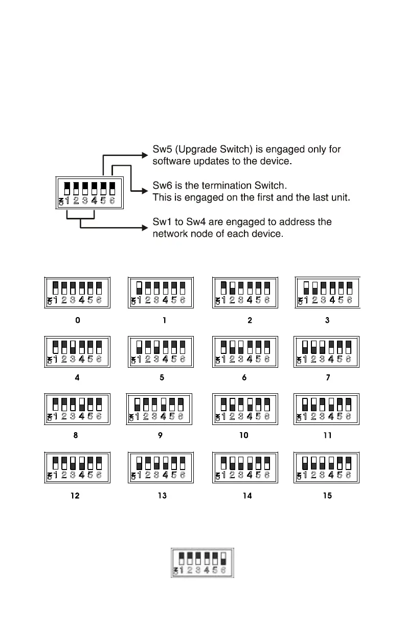
The binary numbering scheme is shown below with the DIP switch.
Settings for Each Node
When using the DRC-SL, leave all switches in the off position
except the Termination switch. Put Sw6 (Termination) to on. The DRC-SL
will then address to Node 16 (As Below)

Questions and Answers:

Question and Answer IconNeed help?

Do you have a question about the zapco DSP6-SL and is the answer not in the manual?

zapco DSP6-SL Specifications

General IconGeneral
Brandzapco
ModelDSP6-SL
CategoryComputer Hardware
LanguageEnglish