EasyManua.ls Logo

Zebra 4 FM

Zebra 4 FM
4 pages
To Next Page IconTo Next Page
Loading...
8
Congratulations again and have fun!
Austria, Belgium, Denmark, Finland,
France, Germany, Greece, Iceland,
Ireland, The Netherland, Italy, Spain,
Norway, Portugal, United Kingdom,
Luxembourg, Sweden, Switzerland
Made in the Philippines
NEON 4 FM INSTRUCTION MANUAL
The following is a listing of replacement parts and
accessories available for the Laser radio series from your hobby dealer.
A. TX Antenna (#58005)
B. Neck strap (#58311)
C. Trainer cord (#58310)
D. Switch harness (#57215S)
E. Heavy duty gold pin switch harness (#54407)
F. Stick extensions (#56381)
G. Flight Preserver (#58480)
4. Replacement Parts & Accessories
- Always turn your transmitter on first and off last.
- Never fly your airplane without first performing a proper range check.
- FCC regulation in the USA prohibits consumers from changing the crystal in the transmitter.
For channel changes send your system to an authorized service/repair center.
- Never fly around or over houses, people or power lines.
- Always charge your batteries before you fly.
- It's a good idea to check your receiver batteries with a tester like the Hitec
Power Mate II (part# 44110). This will verify the charge level in your receiver batteries.
- Always fly responsibly and respect the rights of others.
- Make sure your frequency is clear before turning on your system.
5. Precautions
Zebra 4 FM Instruction Manual
Instruction Manual
Question and Answer IconNeed help?

Do you have a question about the Zebra 4 FM and is the answer not in the manual?

Zebra 4 FM Specifications

General IconGeneral
BrandZebra
Model4 FM
CategoryRemote Control
LanguageEnglish

Summary

Replacement Parts & Accessories

Precautions

System Specifications

Transmitter Features

Details the ergonomically designed 4-channel FM transmitter with precision gimbals, servo reversing, trainer system, battery indicators, and simulator compatibility.

Transmitter Layout

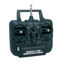
Diagram and labels for the front view of the transmitter, identifying controls like handle, antenna, sticks, trims, and indicators.

Transmitter Specifications

Lists technical details including power supply, current drain, output power, and modulation type (PPM/FM).

Servo Reversing

Explains how to use the servo reversing switches on the transmitter to change the direction of servo rotation for all channels.

Control Stick Adjustment

Information on adjusting the length of the non-slip control sticks to meet user requirements.

Stick Lever Tension Adjustment

Guide on how to adjust the spring tension of control sticks for a preferred feel by accessing the transmitter's rear cover.

Trim Levers

Instructions on using trim levers to correct control surface tracking and proper linkage adjustment after test flights.

LED Battery Indicator

Explanation of the transmitter's LED indicator for battery status (High/Low) and advice to stop flying when it blinks.

Battery Installation

Operation

Installation of Receiver and Servos

Steps for connecting the receiver and servos, emphasizing correct wiring and powering sequence for proper function.

Transmitter, Receiver and Servo Settings

Procedure for checking servo operation, connections, and battery status after installation and setup.

Trainer System

Details on using the trainer system (slave mode only) with a trainer cord and compatibility with flight simulators.

Range Checking

Essential procedure for performing a range check before each operation to ensure control at specified distances.

Related product manuals