Do you have a question about the ZEEWEII DSO1511G and is the answer not in the manual?
Explains the compensation and calibration process for oscilloscope probes.
Discusses the bandwidth differences between 1X and 10X probe settings.
Details the maximum voltage a probe can handle, usually marked on the probe.
Provides advice on using probes, including input capacitance and voltage.
Defines vertical sensitivity and how to adjust it using 'mV' and 'V' buttons.
Explains how to adjust the vertical position of the waveform on the screen.
Defines time base and how to adjust it using 'ns' and 's' buttons.
Describes how to move the waveform left and right in stop mode.
Details methods for adjusting the trigger level for stable waveforms.
Explains the default trigger position and how to move it.
Instructions for turning the oscilloscope on and off using the POWER button.
Guidance on charging the oscilloscope using a USB cable and adapter.
How to adjust vertical sensitivity and time base using specific buttons.
Methods to adjust the trigger level, including manual and automatic options.
Explains the Auto function for automatic time base and vertical sensitivity adjustment.
How to start and stop oscilloscope sampling using the Run/Stop button.
Describes the 50% function to reset waveform position and trigger level.
Explains the Single trigger function for acquiring a single waveform frame.
How to latch and display a reference waveform for comparison.
Steps to capture the current screen display as a screenshot.
How to access and manage stored screenshots.
Details on using the built-in signal generator function.
How to enable AV analog video output to a TV or projector.
Instructions for exporting screenshots to a computer via USB.
How to turn on/off and move horizontal and vertical cursors.
Explains channel settings like coupling modes and probe types.
Lists the available measurement options for signal analysis.
Details trigger modes, types (rising/falling edge), and levels.
Settings for screen persistence, roll mode, and brightness.
Auxiliary menu options, including calibration and FFT analysis.
Configuration options like auto shutdown, sound, language, and USB connection.
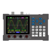
The Zeeweii DSO1511G is a handheld oscilloscope designed for various signal measurement and analysis tasks. It offers a range of functions and features suitable for both beginners and experienced users.
The primary function of the DSO1511G is to capture and display waveforms, allowing users to visualize electrical signals over time. It supports edge triggering, which helps stabilize waveforms on the screen and capture specific segments of interest. The device can operate in "Auto" or "Normal" trigger modes, with "Auto" being suitable for novices as it automatically sets the trigger level, while "Normal" mode requires a trigger event to refresh the display. Trigger types include rising and falling edges, allowing for precise capture based on signal transitions.
The oscilloscope also includes a built-in signal generator, capable of producing sine, square, and triangle waves with adjustable amplitude and frequency. This feature is useful for testing circuits and components. Additionally, it offers a video output function, allowing the display to be mirrored on an external TV or projector, which can be beneficial for presentations or collaborative work.
A screenshot function is integrated, enabling users to capture and save current screen displays. These images can then be viewed directly on the device or exported to a computer via a USB connection, functioning as a U disk for picture transfer.
The DSO1511G is designed for ease of use with a straightforward button interface. The "OK/Auto" button serves a dual purpose: confirming menu selections and initiating an automatic waveform adjustment when the menu is closed. The "Run/Stop" button controls sampling, allowing users to pause and examine captured data or resume live sampling. A long press on this button also activates the square wave generator.
Vertical sensitivity, which determines the voltage represented by each grid on the screen, can be adjusted using the "mV" and "V" buttons. Similarly, the "ns" and "s" buttons control the time base, adjusting the time represented by each horizontal grid. This allows users to zoom in or out on the waveform's time axis to observe high-frequency or low-frequency signals effectively.
The device supports cursor functions for precise measurements. Horizontal and vertical cursors can be activated and moved to measure specific points on the waveform, providing values for voltage differences (dY) and time intervals. The "50%" function quickly returns the waveform to the middle of the screen, resetting vertical offset, trigger position, and trigger level.
For advanced analysis, the DSO1511G includes an FFT (Fast Fourier Transform) option, which can be enabled to perform calculations on the screen waveform and display its frequency spectrum in logarithmic, linear, or "music" (music spectrum) modes.
The device also features a "Reference waveform" function, which latches the previous frame's waveform on the screen. This is particularly useful for single-channel oscilloscopes, allowing users to compare two different waveforms by capturing one, saving it as a reference, and then measuring the second.
Power management includes an auto-shutdown feature, which can be configured to turn off the oscilloscope after 15 minutes of inactivity, conserving battery life. The device can be charged via a USB Type-C cable, with an LED indicator showing the charging status (red for charging, green for fully charged).
Proper probe calibration is crucial for accurate measurements. While the probes included with the device are pre-calibrated, any new probes, especially 10X or 100X probes, must be calibrated before use. This involves connecting the probe to a known square wave signal and adjusting a capacitor on the probe until the waveform is displayed correctly. The manual provides visual guidance for correct and incorrect calibration.
The probe's bandwidth and withstand voltage are important considerations. The 1X probe typically has a bandwidth within 5MHz due to its large input capacitance, while the 10X probe offers standard bandwidth. For measuring high voltages (greater than 40V), it is essential to switch the probe to the 10X position first to attenuate the signal and prevent damage to the oscilloscope's internal circuitry. The maximum withstand voltage for probes is usually marked on the probe itself, typically around 600V (DC+AC).
The device also supports self-calibration, which can be initiated from the "Aux" menu. This is recommended if there is a significant deviation between the waveform position and the zero arrow position, indicating a need for adjustment. Before calibration, users are instructed to remove the probe and USB cable and avoid any operations on the oscilloscope until the process is complete.
To ensure longevity and proper functioning, users are advised to avoid operating the device in humid environments and to keep its surface clean and dry. Charging should be done with a 5V adapter, ensuring the voltage does not exceed 6V. Only authorized personnel should perform maintenance procedures to prevent injury or damage to the product. When exporting screenshots via USB, users are warned not to copy other files to the U disk to prevent potential issues.
| Bandwidth | 100 MHz |
|---|---|
| Channels | 1 |
| Horizontal Scale | 5 ns/div to 50 s/div |
| Time Base Range | 5 ns/div to 50 s/div |
| Trigger Modes | Auto, Normal, Single |
| Trigger Sources | CH1 |
| Vertical Scale | 2mV/div to 10 V/div |
| Rise Time | <3.5 ns |
| Input Impedance | 1 MΩ ± 2% |
| Input Coupling | DC, AC, GND |
| Display | 2.4 inch color TFT |