Do you have a question about the Zeiss VISUCAM lite and is the answer not in the manual?
Unit requires minimal servicing; annual servicing recommended. System check chapter details work plan.
Lists material numbers and English descriptions for tools and test devices required for servicing.
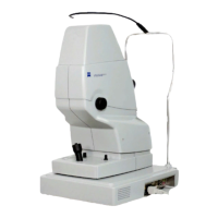
Provides a numbered list of the main components of the VISUCAM lite unit.
Details the functional unit composition and the connections available on the base connector panel.
Lists common questions regarding mechanical operation and movement of the camera head and unit.
Lists common questions regarding electrical issues, software, and system functionality.
Step-by-step instructions for removing and replacing the blinking diode of the fixation light.
Detailed procedure for safely opening and reassembling the camera head.
Instructions for safely replacing the halogen bulb in the camera head.
Procedure for disconnecting and separating the camera head from the main instrument base.
Instructions for replacing the control cable connecting the camera head to the control PCB.
Steps to replace the entire lamp housing assembly, including the PCB.
Procedure for removing and installing the lamp control PCB.
Diagram showing the connectors on the lamp control PCB for identification.
Instructions for replacing the fan that cools the lamp housing.
Procedure for removing and installing the temperature sensor located in the lamp housing.
Steps to replace the shutter mechanism within the camera head.
Instructions for removing and installing the light guide assembly.
Procedures for installing, removing, and replacing components like stepper motor, opto-coupler, filters, and checking the drive.
Details installation, removal, and replacement of stepper motor, opto-coupler, and filters; includes checking the drive.
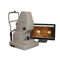
Covers replacing, positioning, focusing, and adjusting the image position of the finder camera.
Includes replacing cameras, stepper motor, opto-coupler, and adjusting horizontal image positions.
Procedure for exchanging the VISUCAM lite control PCB, requiring serial number re-entry.
Steps to remove the camera head assembly, including the instrument base.
Procedure for opening the control base by removing screws and cover.
Instructions for replacing the power supply unit using an Allen key.
Procedure for exchanging the MEDP3 motherboard, requiring removal of the instrument interface GIF.
Steps for backing up data, exchanging the hard disk, and restoring the system via recovery CD.
Reference to 'components of the control base' for exchanging the GIF instrument interface.
Procedure to access system settings, requiring a password ('iris').
Guide to installing drivers using the setup.exe program from a CD.
Options for configuring keyboard settings, speed mode, and language/regional adaptations.
Menu to access printer settings, select default printer, and install new printers.
Instructions for configuring network connection, computer name, workgroup, and IP address.
Procedure to open the Windows Explorer program.
Using ALT+F4 to close an active window.
Using ALT+W to open logserver watch files.
Method to enter BIOS by pressing F2 during instrument booting.
Instructions for installing/uninstalling CD-writer drivers and UDF reader.
Displays information on software version, drivers, and serial number.
Procedure to open the Test Tools program selector.
Describes the three windows available in the Test Tool: Input/Output, Stepper Motors, and Data.
Procedures for testing the focus drive for +25dpt and -25dpt, ensuring sharp image.
Steps to test grabber function and sensor quality using gray filter and capture mode.
Accessing service software data tab to view/edit HW type, dates, serial number, and grabber driver info.
Procedure to enter and save default factory settings for temperature levels and sensors.
Instructions on how data is saved in the VISUCAM lite control system's EEPROM.
Details on temperature levels and their corresponding fan speeds and system shutdown.
Shows currently stored camera positions for B/W and color sensors.
Procedure to check potentiometer input via Rheostat, expecting values ~1-254.
Checking temperature sensor values at different levels and their effects on fan speed/shutdown.
Checking various voltage values (+5V, +12V) using the A/D converter.
Checking supply voltages for LED white, IR, fan, and shutter by switching functions.
Verifying joystick switch and opto-coupler signals for camera movement and light barrier.
Using the service program to adjust brightness lamp levels from 0-200.
Selecting flash brightness and triggering the flash to test its functionality.
Details voltage measurements at specific pins (P22, P23) on the Interface GIF PCB.
Lists voltages present at various points on the VISUCAM lite lamp control PCB.
Describes the contents of the Database folder, including the Visucam.mdb, images, sequences, and TNIs.
Details the Images folder contents, consisting of BMP format images.
Describes the Sequences folder, containing video streams in AVI format.
Details the TNI's folder, containing thumbnails of stored images in JPG format.
Explains the purpose of Save and Update folders for configuration and temporary data.
Indicates this folder contains various drivers for installation.
Notes the location of HP Deskjet driver installations.
Checklist for mechanical integrity: camera head movement, unit security, lens cleanliness, connectors, cables, filters, labels, and glide plate.
Checklist for electrical functions: connections, booting, noise, software start, filter drives, lamp brightness, finder camera, image capture, archiving, printing, and screen settings.
| Image Modalities | Color, Red-Free, Autofluorescence |
|---|---|
| Field of View | 45° |
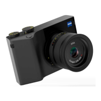
| Light Source | LED |
| Connectivity | USB 2.0 |
| Sensor Type | CCD |
| Working Distance | 30 mm |
| Type | Digital Fundus Camera |
| Image Format | JPEG |
| Compatibility | Windows |