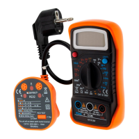
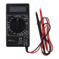
2.7 Content
Operation manual: 1 Test probes: 1 Pair Multimeter : 1 Battery 1.5V AAA: 2
3 Technical characteristics
3.1 General specifications
Function Value
Electrical protection class CAT III 600 V
Pollution degree 2
Calibration Manual
Operating altitude < 2000 m
Operating temperature / humidity: 0°C - 40°C (< 80 %RH)
Storage temperature / humidity: -20 ° C - 60 ° C (<90% RH, Battery removed)
Use Only suitable for indoors
Typical temperature coefficient: 0,1 x Accuracy 0 ° C (<18 ° C or> 28 ° C)
Input voltage max. between the terminals
and the ground
600 V or V~ rms
Function Measuring range
Protection fuse FF : F1 500 mA/600 V - FF : F2 10 A/600 V
Measuring frequency Ca. 3-times / sec
Display LC-Screen 3,5 digits, Max value. : 1999.
Indicator of measuring overflow The digit „1“ will be displayed in the screen
Low battery indicator If the battery voltage drops below the «normal operating voltage»,
the symbol «
+
» appears on the display.
Polarity indicator The symbol "-" appears automatically to indicate a negative polarity.
Power supply Battery 1.5V×2, AAA R03P
Dimensions / Mass 155 (L) x 74 (W) x 40 (H) mm / approx. 155g
3.2 Electrical specifications
Precision: ± (% of reading + number of digits) at a temperature between 18 and 28 ° C with a relative humidity
of <75%; Guarantee for a period of one year.
3.2.1 DC Voltage
Measuring
range
Resolution Accuracy
200mV 0,1mV
± (1.0 % the measured value + 2 digits)
2V 1mV
20V 10mV
200V 100mV
600V 1V ± (1.2% the measured value + 2 digits)
3.2.2 AC Voltage
Measuring
range
Resolution Accuracy
2V 1mV
± (1.2% the measured value + 3 digits)
20V 10mV
200V 100mV
600V 1V ± (1.5% the measured value + 3 digits)
3.2.3 DC Current
Measuring
range
Resolution Accuracy
200µA 0,1µA
± (1.2% the measured value + 2 digits)
2mA 1µA
20mA 10µA
200mA 0,1mA ± (1.5% the measured value + 2 digits)
10A 10mA ± (2.0% the measured value + 3 digits)
3.2.4 AC Current
Measuring
range
Resolution Accuracy
2mA 1µA ± (1.5 % the measured value + 3 digits)
20mA 10µA
200mA 0,1mA ± (2.0% the measured value + 3 digits)
10A 10mV ± (2.5% the measured value + 5 digits)
3.2.5 Resistance
Measuring
range
Resolution Accuracy
200 0,1
± (1.0% the measured value + 3 digits)
2k 1
± (2.0% the measured value + 2 digits)
20k 10
200k 100
2M 1k
20M 10k
± (1.5% the measured value + 3 digits)
3.2.6 Continuity test / diode test
Function Description
If the measured resis-
tance is less than 50 ,
the buzzer will sound.
Open circuit voltage
Approximately 1.8V
The display shows the
approximate voltage drop
Direct DC : approx. 0.6 mA
Reverse DC Voltage:
approx. 2.8 V
3.2.7 Gain (hFE) of a transistor
Function Description
hFE Displays the approx. hFE gain (0-1000). Base current: approx. 10µA - Invert.: approx. 1.8 V
4. Instructions
4.1 DC voltage / AC voltage
Warning - Input voltage max.: 600 V or V~ rms (for the range 200 mV : 250 V or V~ rms).
Do not exceed the specified limits, otherwise there is a risk of electric shock and/or damage to the device.
• Rotate the turning knob to select the appropriate voltage range.
• Plug the red test probe to the input terminal mAVΩ and the black test probe to the COM terminal.
• Connect the test probes to the voltage source or the circuit under test.
Input impedance: 10M .
Input voltage max.: 600 V or
V~ rms. Range 200 mV : 250 V
or V~ rms.
Overload protection:
FF : F1 500 mA/600 V
FF : F2 10 A/600 V
Input current max.
(mA) : 200mA or ~ rms.
10A : continuous (maximum
15 sec.).
Overload protection:
250 V or V~ rms ; do not
measure continuously for more
than 15 seconds.
Overload protection:
250 V or V~ rms ; do not
measure continuously for more
than 15 seconds.
Overload protection:
FF F1 500 mA/600 V
FF F2 10 A/600 V.
Input current max.
(mA) : 200 mA or ~ rms.
10 A : continuous (maximum 15
sec.). Frequency response: 40
Hz-500 Hz in rms of a sine wave
(average response).
Input impedance: 10M .
Input voltage max.: 600 V or
V~ rms.
Frequency response: 40-500Hz
in rms of a sine wave (average
response).
• Read the measured voltage on the screen.
When measuring a DC voltage, the display shows the polarity of the red test probe.
• The display of the number «1» indicates that the value exceeds the upper limit of the selected range.
In this case, select a higher range with the rotary knob.
4.2 Resistance
Warning - Turn off the circuit before measuring resistance, and discharge all capacitors completely.
• Turn the rotary knob to select the corresponding voltage range.
• Connect the red test probe to the input jack “mAV ” and the black test probe to the COM socket.
• Connect the probes to the resistor or to the circuit under test and read the value on the screen.
• When measuring small resistances, shortcircuit the probes and point out the value on the screen. Then connect
the test probes to the resistor being measured and subtract the value of the shorted resistor.
Note :
• If the measured resistance is greater than 1M , wait a few seconds for the display to stabilize. This is com-
mon practice for measuring high resistances.
• When the circuit is open, or when the test leads are not connected, «1» appears on the display.
4.3 DC current / AC current
Warning - To avoid personal injury or damage to the equipment or the material being tested, always
ensure that the rotary switch is in the correct position and that the test leads are connected to the correct sockets
before taking a reading.
• Turn the rotary knob to select the appropriate voltage range.
• Connect the black test probe to the COM jack. If the current to be measured is below 200mA, connect the red
test probe to terminal mA; if it is over 200mA, connect it to the 10A jack.
• Disconnect the circuit and connect the test probes to the tested circuit in series.
• Read the measured current on the display. When measuring a DC current, the display shows the polarity of the
red test probe.
• The display of the number «1» indicates that the value exceeds the upper limit of the selected range. In this
case, select a higher range with the rotary knob.
4.4 Diodes
Warning - Before testing a diode, turn off the power and discharge all capacitors completely.
• Set the rotary knob to .
• Connect the red test probe to the input socket and the black test probe to the COM socket.
• Connect the red test lead to the anode (+) and the black test lead (-) to the diode.
The display shows the approximate voltage drop of the diode. If the test leads are reversed, the number «1» will
be visible on the display.
4.5 Gain hFE of a transistor
Warning - To avoid damaging the device, make sure that the transistor is not connected to any circuit
before the measurements are taken.
• Set the rotary knob to hFE.
• Connect the adapter for transistor test by inserting the «IN» end into the «hFE» input jack and the «COM» end
into the «COM» jack.
• Insert the transistor into the corresponding slots (NPN or PNP) of the adaptor to perform the measurement.
• Read the gain of the transistor on the display screen.
4.6 Continuity test
Warning - Before carrying out a continuity test, switch off the circuit and discharge all capacitors
completely.
• Set the rotary knob to .
• Reliez le cordon rouge à la borne d’entrée “mAV ” et le cordon noir à la borne COM.
• Raccordez les cordons au circuit testé.
• Connect the red test probe to the input jack and the black test jack to the COM jack.
• Connect the test leads to the circuit under test.
If the measured resistance is less than 50 the buzzer sounds.
5. Maintenance
5.1 Cleaning the device
Warning - Before opening the rear cover, switch off the device and disconnect the probes from any
circuit.
Clean the device with a damp cloth impregnated with a mild detergent (not chemical solvents).
Dirt or moisture on the input jacks can lead to incorrect measurements.
To clean the input jacks:
• Turn the rotary knob to OFF and remove the test probes.
• Carefully clean all input jacks.
• Take a cotton swab soaked in solvent or grease to clean the jacks.
Change the cotton swab for each jack to prevent contamination.
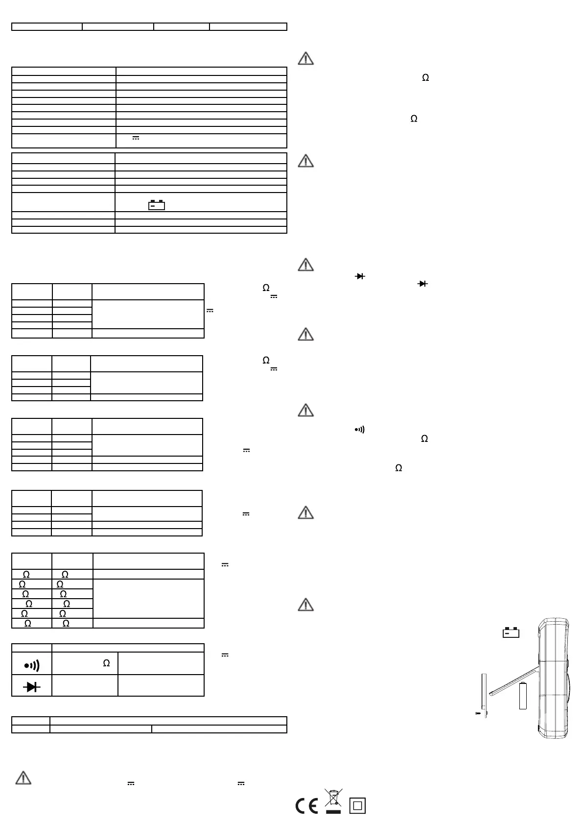
5.2 Battery replacement
Warning - Before opening the back cover, switch off the device and disconnect the test probes from the
circuits under test.
To replace the battery (see opposite figure):
• If the battery voltage falls below the «normal operating voltage», then the symbol «
+
»
appears on the screen.
• Set the rotary knob to OFF.
• Remove the test probes from the input jacks.
• Unscrew the battery compartment cover and remove it.
• Replace the old battery with a new one of the same type.
• Mount the cover and fix it again.
20200318
HBF SAS
Z.I Bonzom
09270 Mazères - France

 Loading...