Do you have a question about the Zenitel Vingtor Stentofon 1008015000 and is the answer not in the manual?
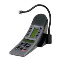
Overview of the IP Desktop Master Station for general use, featuring a display and direct access keys.
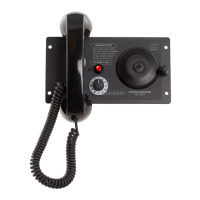
Details the IP Operating Room (OR) Master Station for specialized environments like clean rooms.
Describes the IP Flush Master Station suitable for control and guard rooms, featuring call queuing.
Covers the IP Dual Display Station for desktop use in banking or offices, with dual displays.
Explains how to configure the station using its physical keypad and offline menu.
Details accessing and configuring the station via its embedded web server using a browser.
Covers configuring the station mode (SIP/Alphacom/Pulse) and IP settings (DHCP/Static IP).
Provides detailed configuration options for SIP account, server domains, and authentication.
Configures speaker volume, noise reduction, microphone sensitivity, and speaking modes.
Details the configuration of Direct Access Keys (DAKs) and input buttons for quick dialing and functions.
Explains configuration for SNMP, including trap settings and network access.
Describes setting up automatic configuration by polling settings from a TFTP server.
Introduces advanced, non-mandatory configuration settings for the station.
Details configuring VLAN settings (802.1Q) for network segmentation and traffic management.
Explains how to configure 802.1X network access control for device authentication.
Outlines the requirements and setup for using a TFTP server for software upgrades.
Describes the step-by-step process for manually upgrading station software via TFTP.
Explains how to configure automatic software updates by polling a TFTP server.
Describes the RJ45 LAN connector (P1) for Ethernet and Power over Ethernet (PoE).
Details the 6-pin screw terminal (P3) for external connections like loudspeakers and relays.
Explains the P4 connector for 24 VDC power and input signals like station LED.
Describes the 18-pin ZIF connector (J4) for the keyboard and its matrix.
Details the 20-pin ZIF connector (J5) for LCD displays.
Covers the RJ45 connector (J1) for the I2C interface used with DAK modules.
Describes the 3-pin header (J7) for connecting a gooseneck microphone.
Details the connector (J8) for connecting the handset, including pinout.
Explains the 6-pin header (J9) for connecting an external amplifier.
Details the pins for the internal microphone connection.
Describes the pin headers (J11, J12, J13) for handset and headset connections.
Explains the slide switch (S1) for selecting internal or gooseneck microphone.
Mentions the 4-way DIP switch (S3) for future use, to be left in OFF position.
Describes the Station LED (LED4) and its flashing patterns indicating connection status.
Details the Status LED (LED3), a bicolor LED indicating registration status.
Explains the Power LED (LED6) indicating power status and potential faults.
Describes the LEDs on the LAN (P1) and AUX (P2) ports indicating Ethernet connection and speed.
Provides steps to restore factory defaults on stations equipped with a display.
Outlines the procedure to reset stations without a display to factory defaults.
Explains how IP stations can automatically poll configuration files from a TFTP server.
Details general parameters related to automatic software updates, like interval and image type.
Lists and describes essential SIP parameters like SIP ID, domain, and authentication.
Covers parameters for call handling, including speed dial numbers and IP backups.
Details parameters for SNMP configuration, including trap receivers and community strings.
Presents example configuration files for device-specific settings.
Provides an example of a configuration file tailored for a specific IP station.
Shows an example of a global configuration file, noting parameters that are ignored.
| Model | Vingtor Stentofon 1008015000 |
|---|---|
| Part Number | 1008015000 |
| Frequency Response | 300 Hz - 3.4 kHz |
| Ingress Protection | IP66 |
| Operating Temperature | -25°C to +55°C |
| Housing Material | Aluminum |
| Mounting Type | Wall |