AM/FM/MULTIPLEX ALIGNMENT
GENERAL
These receivers have been aligned at the factory and normally
will not require further adjustment. As a result, it is not
recommended that any attempt be made to alter the stages.
If any components are replaced or if anyone tampers with
the adjustments, realignment may be necessary.
AM ALIGNMENT
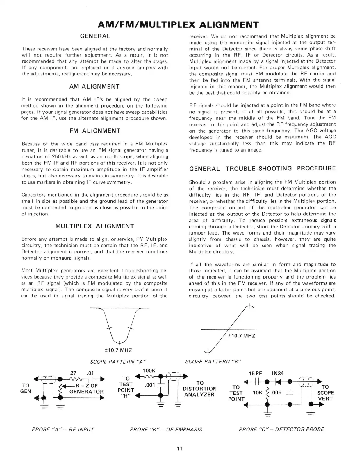
It is recommended that AM IF's be aligned by the sweep
method shown in the alignment procedure on the following
pages.
If your signal generator does not have sweep capabilities
for the AM IF, use the alternate alignment procedure shown.
FM ALIGNMENT
Because of the wide band pass required in a FM Multiplex
tuner, it is desirable to use an FM signal generator having a
deviation of 250kHz as well as an oscilloscope, when aligning
both the FM IF and RF portions of this receiver. It is not only
necessary to obtain maximum amplitude in the IF amplifier
stages,
but also necessary to maintain symmetry. It is desirable
to use markers in obtaining IF curve symmetry.
Capacitors mentioned in the alignment procedure should be as
small in size as possible and the ground lead of the generator
must be connected to ground as close as possible to the point
of injection.
MULTIPLEX ALIGNMENT
Before any attempt is made to align, or service, FM Multiplex
circuitry, the technician must be certain that the RF, IF, and
Detector alignment is correct, and that the receiver functions
normally on monaural signals.
Most Multiplex generators are excellent troubleshooting de-
vices because they provide a composite Multiplex signal as well
as an RF signal (which is FM modulated by the composite
multiplex signal). The composite signal is very useful since it
can be used in signal tracing the Multiplex portion of the
SCOPE PATTERN "A "
receiver. We do not recommend that Multiplex alignment be
made using the composite signal injected at the output ter-
minal of the Detector since there is alway some phase shift
occurring in the RF, IF or Detector circuits. As a result,
Multiplex alignment made by a signal injected at the Detector
input would not be correct. For proper Multiplex alignment,
the composite signal must FM modulate the RF carrier and
then be fed into the FM antenna terminals. With the signal
injected in this manner, the Multiplex alignment would then
be the best that could possibly be obtained.
RF signals should be injected at a point in the FM band where
no signal is present. If at all possible, this should be at a
frequency near the middle of the FM band. Tune the FM
receiver to this point and adjust the RF frequency adjustment
on the generator to this same frequency. The AGC voltage
developed in the receiver should be maximum. The AGC
voltage substantially less than this may indicate the RF
frequency is tuned to an image.
GENERAL TROUBLE-SHOOTING PROCEDURE
Should a problem arise in aligning the FM Multiplex portion
of the receiver, the technician must determine whether the
difficulty lies in the RF, IF, and Detector portions of the
receiver, or whether the difficulty lies in the Multiplex portion.
The composite output of the multiplex generator can be
injected at the output of the Detector to help determine the
area of difficulty. To reduce possible extraneous signals
coming through a Detector, short the Detector primary with a
jumper lead. The wave forms and their magnitude may vary
slightly from chassis to chassis, however, they are quite
indicative of what will be seen when signal tracing the
Multiplex circuitry.
If all the waveforms are similar in form and magnitude to
those indicated, it can be assumed that the Multiplex portion
of the receiver is functioning properly and the problem lies
ahead of this in the FM receiver. If any of the waveforms are
missing at a latter point but are apparent at a previous point,
circuitry between the two test points should be checked.
SCOPE PATTERN "B"
PROBE "A" - RF INPUT
PROBE "B"- DE-EMPHASIS
PROBE "C"- DETECTOR PROBE
11
 Loading...