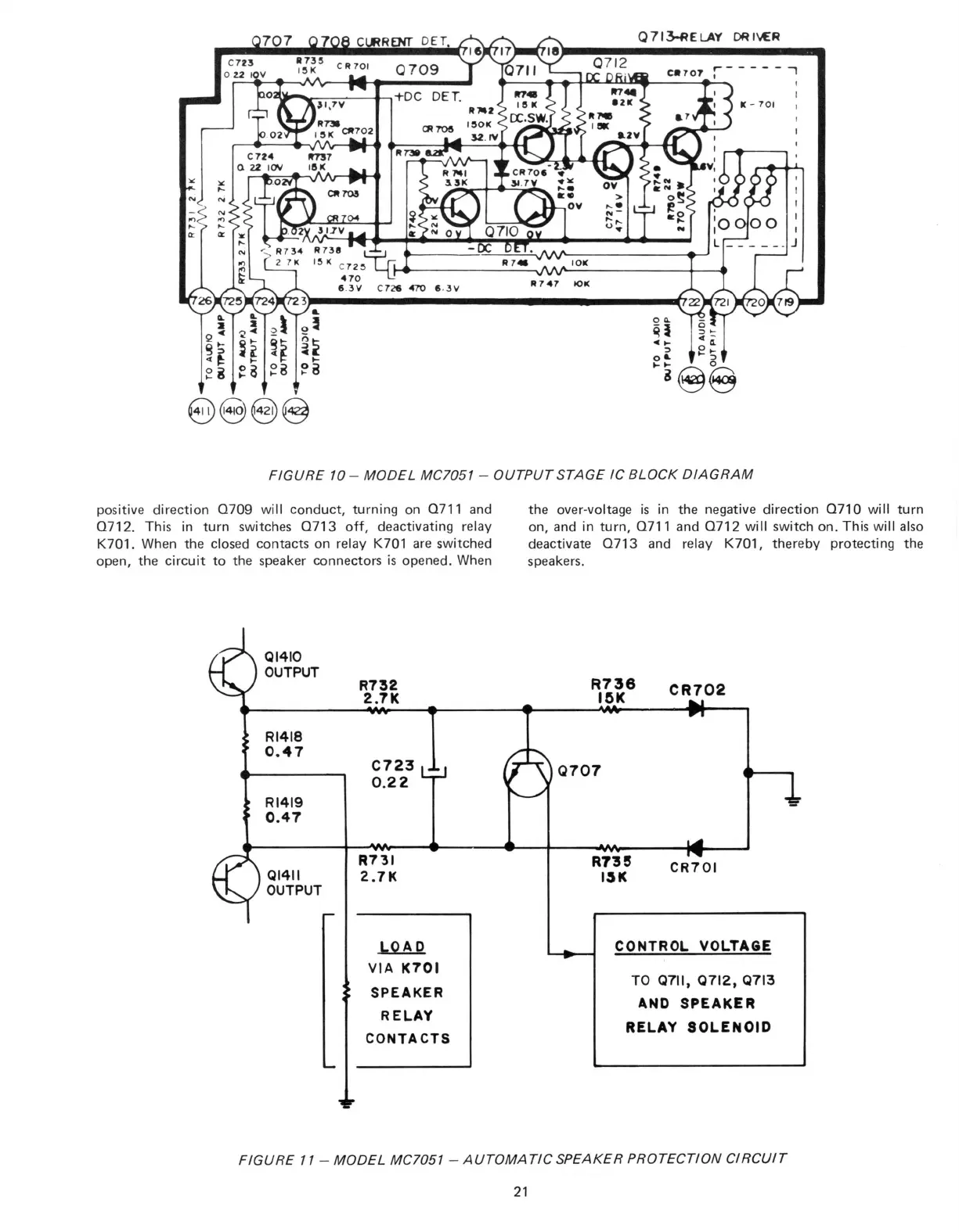
FIGURE 10 - MODEL MC7051 - OUTPUT STAGE IC BLOCK DIAGRAM
positive direction Q709 will conduct, turning on Q711 and
Q712.
This in turn switches Q713 off, deactivating relay
K701.
When the closed contacts on relay K701 are switched
open,
the circuit to the speaker connectors is opened. When
the over-voltage is in the negative direction Q710 will turn
on,
and in turn, Q711 and Q712 will switch on. This will also
deactivate Q713 and relay K701, thereby protecting the
speakers.
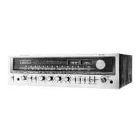
FIGURE 11 - MODEL MC7051 - AUTOMATIC SPEAKER PROTECTION CIRCUIT
21