Current overload protection occurs when excess current is
sensed through R1418 and R1419. These currents will flow via
R731 and R732. Small overloads will develop a voltage between
base and emitter of Q707, causing Q707 to conduct, CR705
will be biased on, applying bias to Q711. Q711 will turn Q712
on and Q713 off, deactivating K701. When higher overload
currents exist, they will cause a larger voltage across Q707's
base emitter junction. This will cause diodes CR701 and
CR702 to turn on, providing protection for Q707.
An added circuit function is the protection of output circuitry
used in these models if the external load impedance is below
the design limit. A low load impedance could exist if:
1.
Wrong impedance speakers were connected. CAUTION —
One four ohm and one eight ohm speaker would result in
an effective load impedance that is below the design limit.
2.
Shorted voice coil winding, or other circuit defect.
One eight ohm speaker connected to each "A" and "B" speaker
output results in the minimum recommended load impedance.
As long as the effective load impedance is greater than approx-
imately three ohms, the resistance ratio of R735/R731 will
closely match the ratio of R1419/Load. The same would also
be true of ratios R736/R732 and R1418/Load. Under this
condition, voltages from outputs will not overcome the oppos-
ing voltages developed by diodes CR701 and CR702. This
maintains transistor Q707 at "cut-off".
If the load impedance drops below approximately three ohms,
the ratios change, causing the emitter voltage of Q707 to go
negative and the base voltage to go positive. This will forward
bias Q707, turning it "on". When Q707 conducts, it will
activate the remainder of the circuitry, causing speaker relay
K701 to open, disconnecting the low impedance load, thereby
protecting the receivers output circuitry.
SPEAKER CONNECTORS
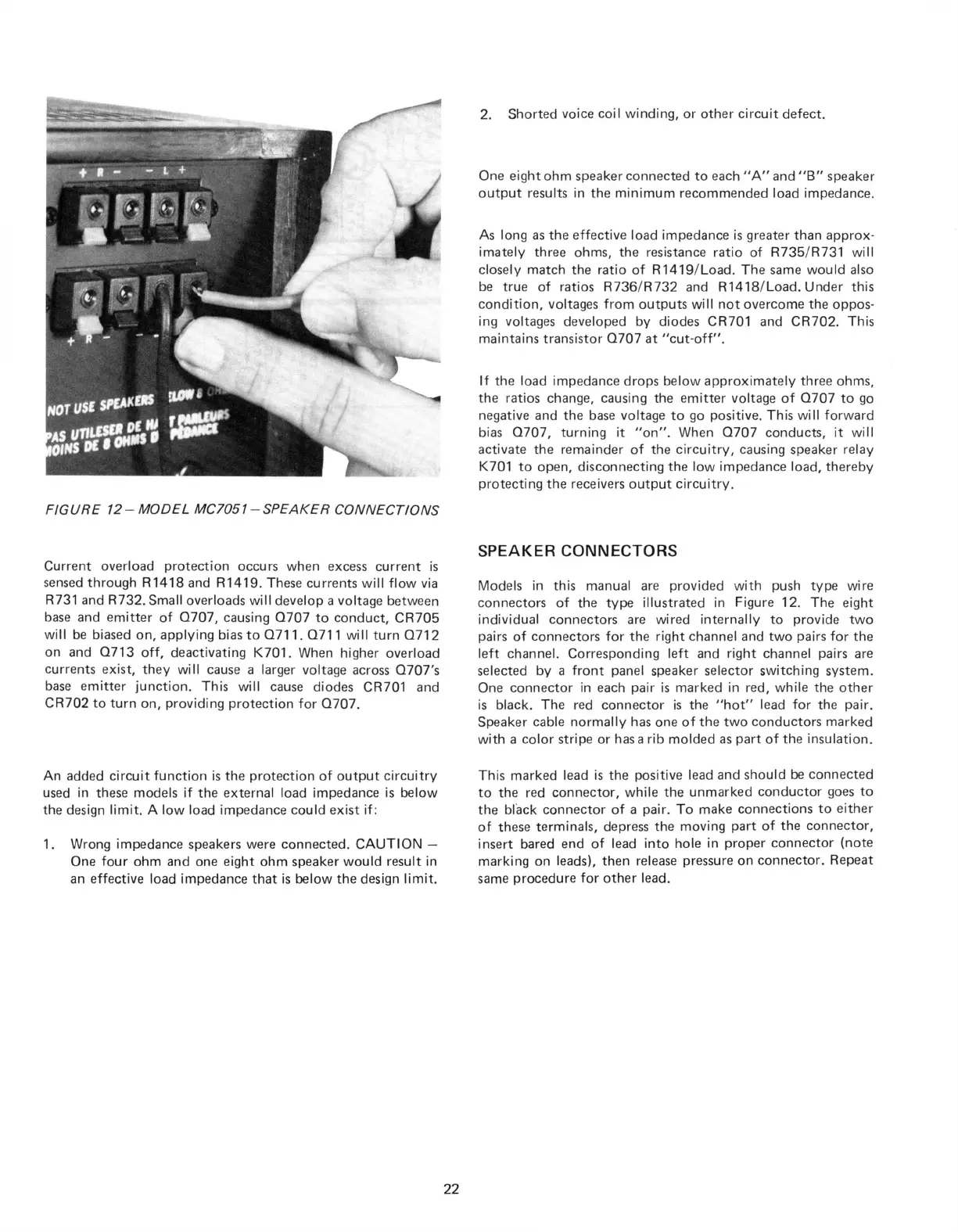
Models in this manual are provided with push type wire
connectors of the type illustrated in Figure 12. The eight
individual connectors are wired internally to provide two
pairs of connectors for the right channel and two pairs for the
left channel. Corresponding left and right channel pairs are
selected by a front panel speaker selector switching system.
One connector in each pair is marked in red, while the other
is black. The red connector is the "hot" lead for the pair.
Speaker cable normally has one of the two conductors marked
with a color stripe or has a rib molded as part of the insulation.
This marked lead is the positive lead and should be connected
to the red connector, while the unmarked conductor goes to
the black connector of a pair. To make connections to either
of these terminals, depress the moving part of the connector,
insert bared end of lead into hole in proper connector (note
marking on leads), then release pressure on connector. Repeat
same procedure for other lead.
22
FIGURE 12-MODEL MC7051 - SPEAKER CONNECTIONS
 Loading...