Do you have a question about the Zenith Royal 1000 and is the answer not in the manual?
Describes the transistor portable chassis as a conventional super-heterodyne receiver with specific IF stages.
Details the receiver's frequency ranges and the power supply requirements using Zenith Z2NL batteries.
Explains how to tune RF, mixer, and oscillator coils using hex-holes and alignment wrenches.
Stresses the importance of removing transistors before resistance measurements to avoid incorrect readings.
Suggests using a VTVM with a good low range scale for accurate circuit voltage measurements.
Advises removing transistors when soldering at the socket base to prevent heat damage.
Notes the current lack of satisfactory commercially available transistor testers.
Lists essential equipment for transistor radio repair, including signal generators, VTVM, and tools.
Warns against 'screwdriver testing' and recommends point-to-point signal checking for diagnostics.
Provides detailed steps for aligning IF, BC, and SW stages using specific signal inputs and trimmers.
Diagram and description of the dial cord drive mechanism, including cord routing and turns.
Diagram showing the physical location of transistors, trimmers, and other components on the chassis.
Presents the overall circuit schematic illustrating all major components and their interconnections.
Provides essential notes on component tolerances, voltage measurement conditions, and capacitor replacement.
| Type | Transistor Radio |
|---|---|
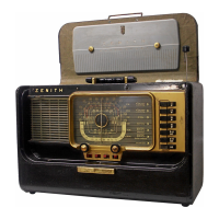
| Model | Royal 1000 |
| Manufacturer | Zenith |
| Tuning | Analog |
| Material | Plastic and Metal |
| Wave bands | AM, FM |
| Bands | AM, FM |
| Power Source | Battery |