Do you have a question about the Zenith 1937 and is the answer not in the manual?
Introduction to Zenith's 1937 automobile radio receivers and models.
Circuit diagram for 4-tube models, including component list and specifications.
Circuit diagram for 5-tube models, listing components and specifications.
Circuit diagram for 7-tube models, detailing components and specifications.
Circuit diagram for 10-tube models, listing components and specifications.
Circuit diagram for model 5-M-191, including components and specifications.
Socket voltage measurements for specific 1937 Zenith models.
Socket voltage data for 6-tube Zenith radio models.
Socket voltage measurements for 5-tube Zenith radio models.
Socket voltage data for the 8-M-195 Zenith radio model.
Step-by-step guide for aligning the 5406 chassis receiver.
Step-by-step guide for aligning the 5633 chassis receiver.
Alignment steps for multiple chassis types, covering IF, oscillator, and RF.
Step-by-step guide for aligning the 1203 chassis receiver.
Troubleshooting common issues for the 1004 Chassis model.
Guidelines for connecting and optimizing antenna performance.
Procedures to diagnose and fix ignition interference issues.
List of parts for dial and drive mechanisms.
List of radio frequency coils, chokes, and IF transformers.
List of condensers and resistors with part numbers and prices.
List of miscellaneous items including sockets, switches, and knobs.
Definitions for tube classes, grid nomenclature, and pin identification.
Table detailing basing connections for Zenith tubes with octal bases.
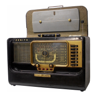
| Model | Zenith 1937 |
|---|---|
| Category | Receiver |
| Tuning principle | Superheterodyne |
| Wave bands | AM, Shortwave |
| Loudspeaker | Dynamic |
| Power out | 5 Watts |
| Material | Wood |
| Shape | Table model |
| Power Supply | AC |
| Speakers | 1 |