Installation (cont’d)
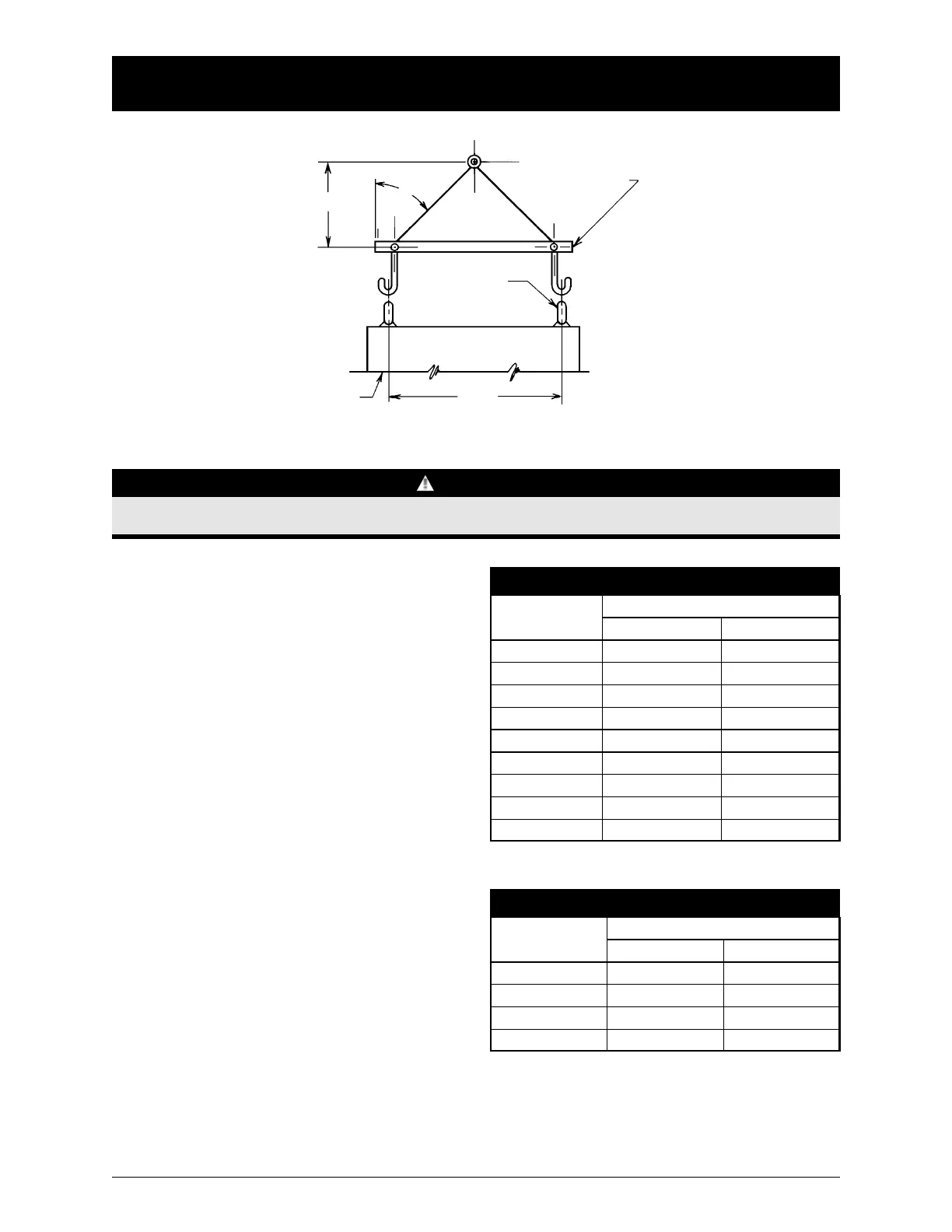
D
CABINET
LIFTING EYES
SPREADER BAR
H
45°
Figure 1
NOTICE
When lifting the switch using a spreader bar, height H must be equal to half of distance D.
Power Connections
Zenith transfer switches are supplied with
UL listed solderless screw type terminals
as standard for the Normal, Emergency and
Load power connections. Table 1 lists the
number and sizes of cable lugs supplied
as standard for each switch amp rating.
Connect the Normal, Emergency, and Load
conductors to the clearly marked terminals
on the transfer switch. R
emove surface
oxides from cables by cleaning with a wire
brush. Verify that all connections are cor
-
rect before tightening the lugs. All cable
lug connections must be tightened to the
proper torque values as shown in T
able 2.
Do not run cables or wiring behind front-
connected transfer switches.
In cases where the Normal, Emergency and
Load connections are made to a rear con-
nected bus bar, a compression washer, flat
washer, and a minimum grade 5 bolt must
be used and torqued to the values in T
able 3.
Tightening Torque for Lugs
Socket Size
Across Flats
Torque
Lb. - In. Lb. - Ft.
1/8 45 4
5/32 100 8
3/16 120 10
7/32 150 12
1/4 200 17
5/16 275 23
3/8 375 31
1/2 500 42
9/16 600 50
Tightening Torque for Bus Bars
Bolt Size
Torque Bolt (Grade 5)
Lb. - In. Lb. - Ft.
1/4-20 72 6
5/16-18 132 11
3/8-16 300 25
1/2-13 720 60
Table 2
Table 3
Zenith Controls, Inc.
ZTSH Operation and Maintenance Manual (43R-1000)
3
 Loading...