Installation (cont’d)
Screw Type Terminals for External Power Connections
Switch Size
(Amps)
Normal, Emergency & Load Terminals Fully Rated Neutral Bar (When Required)
Cable Per Pole Range of Wire Sizes No. of Cables Range of Wire Sizes
40 1 #8 to 2 AWG 3 #8 to 1/0 AWG
80 1 #8 to 1/0 AWG 3 #8 to 1/0 AWG
100 1 #8 to 1/0 AWG 3 #8 to 1/0 AWG
150 1 #8 to 3/0 AWG 3 #6 AWG to 300 MCM
225 1 #6 AWG to 250 MCM 3 #6 AWG to 300 MCM
260 1 #6 AWG to 350 MCM 3 #6 AWG to 300 MCM
400 1 #4 AWG to 600 MCM 4 #2 AWG to 600 MCM
600 2 #2 AWG to 600 MCM 8 #2 AWG to 600 MCM
800 4 #2 AWG to 600 MCM 12 #2 AWG to 600 MCM
1000 4 #2 AWG to 600 MCM 12 #2 AWG to 600 MCM
1200 4 #2 AWG to 600 MCM 12 #2 AWG to 600 MCM
1600
2000
3000
4000
Line and load terminals are located
in rear and arranged for bus bar
connection.
12
12
12
12
3/0 AWG to 750 MCM
3/0 A
WG to 750 MCM
3/0 AWG to 750 MCM
3/0 AWG to 750 MCM
Table 1
Control Connections
A complete information package is furnished with each
transfer switch including a complete connection diagram
and schematic which details all necessary control circuit
field connections.
The engine start control wires connect to the terminals
specified in the upper left corner of the control panel.
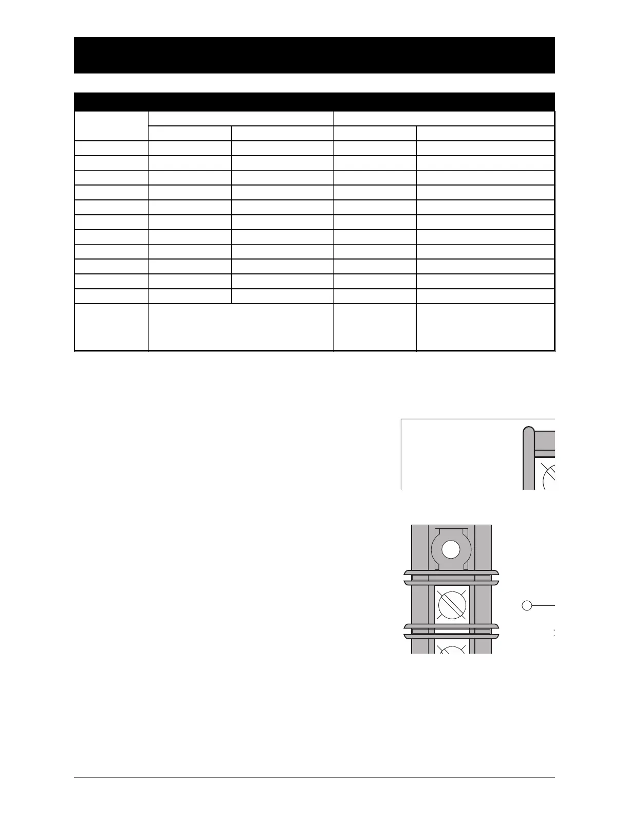
F
igure 2 shows the location of these terminals on the stan
-
dard SSRCP printed circuit board mounted on the steel
backplate. These terminals are clearly identified by a pre-
printed label attached to the steel control panel. In the
case of manual transfer switches, or in other applications
not requiring the standard control panel, clearly marked
terminal blocks are provided in the upper left corner of
the control panel for the engine start control wires.
Terminals for field connections to the A3 Emergency auxil-
iary contacts and the A4 Normal auxiliary contacts are also
provided. These terminals are clearly marked and appear on
the side of the power panel. On 400 amp units these terminals
appear on the disconnect switch bracket above the operator
handle, and are marked as illustrated in F
igure 3.
 Loading...