7
Notes ball valves
■ Mount ball valves up- and downstream of the
meter.
■ Mount a ball valve with bore M10x1 for direct
sensors in the supply. This is required for the
installation of the supply sensor
■ For symmetrical temperature sensor installa-
tion, mount an identical ball valve in the return.
This one is used for mounting the return sensor.
Mounting heating- / cooling energy meter
■ Flush the system thoroughly before installing
the heating-/cooling energy meter.
■ Close valves and release pressure.
■ Dismount the existing ow sensor or meter blank.
■ Use only new and awless sealing material
and check the seal face for damage.
■ Install the new ow sensor according to the
correct ow direction and installation position.
■ Turn heat computer to desired reading position.
Information: The best measuring results can be
achieved by mounting with horizontal diallevel.
Combi-devices are, for example, used in tight
installation points without room for the calculator
on the ow sensor or when the calculator is dif-
cult to read. Therefore the device still remains
easy to read enabling optimum use of the space
available for installation of the ow meter.
Installing the temperature sensor
■ The installation of the temperature sensors
should be preferably symmetrical and direct
installation.
■ Do not remove the return sensor if already
mounted in the VMU.This is also valid for all
the safety seals which are mounted on the de-
vice as standard.
■ Sensors are colour-coded (red = supply, blue
= return).
■ The connecting cables may not be buckled, ex-
tended or shortened.
■ The seal at the sensor installation point on the
measuring capsule may not be damaged.
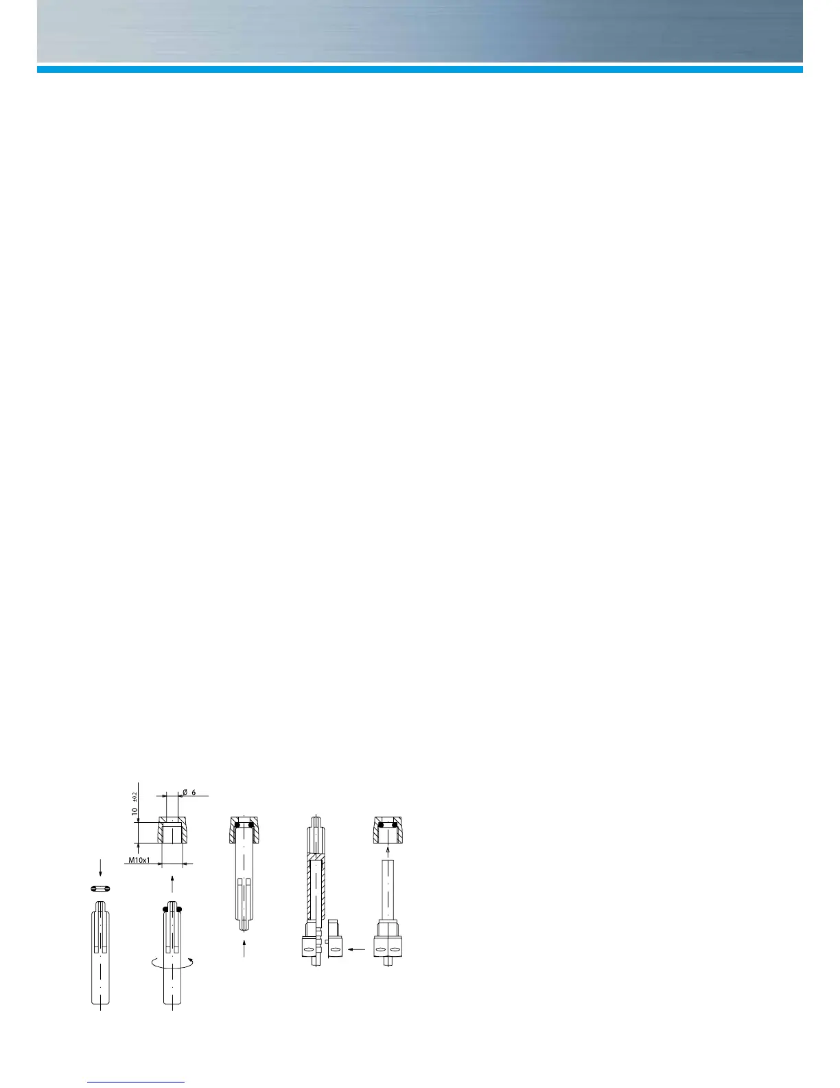
■ Remove locking screw and seal at the ball
valve completely, if existing.
■ Attach the O-ring to the installation aid (the 2nd
O-ring is only a spare O-ring).
■ Using the installation aid, insert the O-ring into
the installation point according to DIN EN 1434
with a slight circular motion.
■ Using the other end of the installation aid bring
the O-ring into the correct position.
■ Insert the 2 halves of the plastic connector into
the sensor’s three notches (crimps) and press
them together.
■ Use the installation aid as positioning aid.
■ Insert the temperature sensor into the installa-
tion point and screw it in tightly until the dead
stop of the seal on the 12-point is reached
(mounting torque 3-5 Nm).
■ The sensor optional integrated in the VMT has
to be secured
■ Secure the sensor after installation against
unauthorised removal with appropriate sealing
(available as a sealing set).
Montage DF- Adapter

 Loading...