© Zennio Avance y Tecnología S.L. Edition 11 Further information www.zennio.com Page 1/2
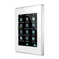
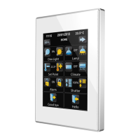
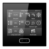
Z41 Pro
Capacitive color touch panel with IP connection
ZVI-Z41PRO TECHNICAL DOCUMENTATION
FEATURES
• 4.1’’ capacitive color touch panel (320x240 pixels)
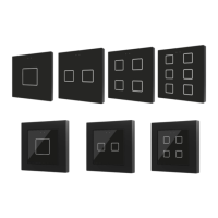
• Available in the following colors: silver (Pantone 10105C), anthracite black
(Pantone Black U), white (NCS 500-N) and gloss white (Pantone RB82798)
• 16 million color LCD display
• Up to 12 configurable pages
• Up to 96 configurable direct control and/or indicator functions
• 2 independent thermostats
• 2 analog/digital inputs
• Customized device orientation (Vertical or Horizontal)
• Built-in temperature sensor
• Real Time Clock (RTC) with watch battery and NTP support
• External 12-29 VDC power supply
• Integrated KNX BCU (TP1-256)
• Mini-USB and Ethernet connection
• Magnetic fit
• Complete data saving in case of power failure
• Conformity with the CE, UKCA, RCM directives (marks on the back side)
10. External power supply connector
Programming button: short press to set programming mode. If this button is held while plugging the device into the KNX bus, it enters the safe mode.
Programming LED: programming mode indicator (red). When the device enters the safe mode, it blinks (red) every half second. During the start-up
(reset or after KNX bus failure) and if the device is not in safe mode, it emits a red flash.
Electric operation control device
Typical TP1 bus connector for 0.8 mm Ø rigid cable
12-29 VDC. Maximum consumption: 250 mA (12 VDC), 112 mA (24 VDC),
86 mA (29 VDC). Do not connect 29 VDC KNX bus as external power
supply
Complementary characteristics
Portrait or landscape position, with the temperature sensor at the bottom or
right, respectively. Magnetic fit. See Installation instructions section.
Please, keep away from heat and cold air flows to get better temperature
measurements.
Response on KNX bus failure
Data saving according to parameterization. Initialization screen.
Response on KNX bus restart
Data recovery according to parameterization
Response on power supply failure
Complete data saving. Display is switched off
Response on power supply recovery
Several on display as programmed
RJ45 cable connector (included). Mini USB A-B cable Ref. ZN1AC-UPUSB
(not included)
PC+ABS FR V0 halogen free
¹ Maximum consumption in the worst-case scenario (KNX Fan-In model).
Ref. ZN1-HOLDER
(included)