Do you have a question about the ZETTLER FLAMEVision FV400 Series and is the answer not in the manual?
| Power Supply | 24 VDC |
|---|---|
| Operating Voltage | 18-30 VDC |
| IP Rating | IP66 |
| Detection Principle | Infrared |
| Field of View | 90° horizontal |
| Humidity | Up to 95% RH, non-condensing |
| Output | Relay contact |
Points to FV400 Series Product Information and Design Application guide for specifications.
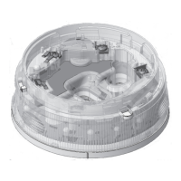
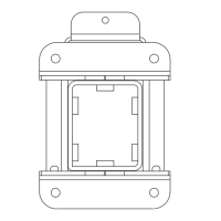
Details direct mounting and mounting using a bracket for the FV400 detector.
Crucial safety advice for mounting, including power handling and stable structures.
Guidance on the temporary weatherproof cover for protecting wiring before final installation.
Instructions for fitting and removing the optional weather hood for enhanced environmental protection.
Key safety warnings and recommended cable specifications for detector wiring.
Guidelines for routing detector cables to prevent interference and ensure signal integrity.
Mandatory procedures for sealing cable glands and stopping plugs to maintain enclosure integrity.
Step-by-step instructions for correctly fitting the EMC clamp for electromagnetic compatibility.
Details on main/loop power input and ancillary power sources for detector functions.
References to detailed wiring diagrams for various detector interface options.
Diagram and explanation of link settings for the detector's relay output functionality.
Illustrates the wiring connections required for the detector when operating in an MX Loop system.
Provides wiring details and link configurations for the 4-20 mA sink output mode.
Details wiring and link settings for the 4-20 mA source output mode of the detector.
Diagram showing wiring for a conventional zone setup, including End of Line resistor placement.
Diagram and link configuration for providing Ancillary Power to detector options like heater or RS485.
Wiring diagram for connecting RS485 communication and video output interfaces to the detector.
Diagram illustrating the wiring for walk-test input signals and remote LED indicators.
Instructions for configuring basic detector functions using DIP switches located on the unit's back panel.
Table detailing interface mode selections and their possible combinations for detector operation.
Details on configuring alarm delays, detection ranges, and MX loop addressing.
Critical system checks and warnings for ensuring correct detector installation and operation.
Procedures for performing wiring integrity tests and functional validation of the installed detectors.
References to further documentation for advanced configuration tools and diagnostic procedures.