Do you have a question about the ZIEHL-ABEGG Ucontrol PXDM10A and is the answer not in the manual?
| Brand | ZIEHL-ABEGG |
|---|---|
| Model | Ucontrol PXDM10A |
| Category | Controller |
| Language | English |
Copyright notice for the operating instructions.
Basis of device construction and safety regulations.
Guidelines for device operation and safety advice.
Instructions for safe transport and storage of the device.
Owner's responsibilities for safe operation and safeguarding hazardous areas.
Explanation of safety symbols and warning information.
Safety precautions for electrical work and equipment.
Testing procedures according to accident prevention directives.
Recommendations for using approved accessories and spare parts.
Contact information for the manufacturer and service department.
Description of the device's intended applications for motors.
Technical specifications including current, heat dissipation, and housing protection.
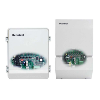
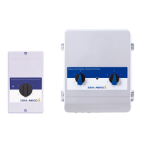
Overview of different Ucontrol device versions (IP54 and IP20).
Guidelines for wall-mounting and cabinet installation.
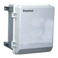
Conditions for outdoor installation in IP54 housing.
Advice on avoiding condensation during commissioning.
Recommendations for systems with current-operated circuit-breakers.
Information on potential at control voltage connections.
Guidelines for cable installation and managing interference.
Requirements for electrical installations.
Explanation of power derating due to ambient temperature.
Guidelines for connecting the mains power supply.
Requirements for the voltage supply.
Instructions for connecting the motor.
Information and mitigation for motor noise.
Methods for protecting the motor.
Connecting signals to analog inputs.
Details on the 0-10V analog output.
Providing voltage supply for external devices.
Functions and connections for relay outputs.
Functions and connections for digital inputs.
Connecting the external terminal.
Connecting the RS-485 interface for MODBUS communication.
Description of the multipurpose LC display and its symbols.
How to navigate and understand the menu structure.
Overview of the different menu groups.
Initial start-up procedures and settings.
Process for entering the PIN for menu access.
Setting the display language of the device.
Procedure for resetting the device to a default state.
Querying the currently set operating mode.
Displaying the device software version.
Information display for selected operating modes.
Info screen for speed controller mode 1.01.
Info screen for various controller modes.
Display and query of device events and malfunctions.
Choosing the appropriate operating mode for the application.
Initial device settings for speed controller mode.
Configuration of parameters for speed controller operation.
Illustrative diagrams of signal and output voltage characteristics.
Detailed menu structure for speed controller configuration.
Default and user-configurable settings for mode 1.01.
Initial device settings for temperature control modes.
Using analog input 2 for sensors or external setpoints in temperature control.
Configuration settings for various temperature control modes.
Illustrative diagrams of temperature control functions.
Using the 0-10V output for additional functions in mode 2.03.
Using relay outputs for heating or cooling control in mode 2.03.
Monitoring temperature with alarm functions in mode 2.03.
Menu plan for temperature control and outdoor dependency.
Menu plan for temperature control with additional functions.
Menu plan for two-sensor temperature control.
Default and user settings for modes 2.01-2.05.
Initial device settings for condenser pressure control modes.
Using analog input 2 for sensors or external setpoints in pressure control.
Configuration settings for condenser pressure control modes.
Illustrative diagram of pressure control function.
Menu plan for pressure control with refrigerant input.
Menu plan for dual circuit condenser pressure control.
Default and user settings for modes 3.01-3.04.
Initial device settings for ventilation pressure control.
Using analog input 2 for sensors or external setpoints in ventilation pressure control.
Configuration settings for ventilation pressure control modes.
Adjusting setpoint based on outdoor temperature for ventilation pressure control.
Menu plan for air conditioning pressure control.
Pressure control dependent on outdoor temperature.
Default and user settings for modes 4.01-4.02.
Initial device settings for volume control modes.
Using analog input 2 for sensors or external setpoints in volume control.
Configuration settings for volume control modes.
Adjusting setpoint based on outdoor temperature for volume control.
Menu plan for air conditioning volume control.
Volume control with setpoint dependent on outdoor temperature.
Default and user settings for modes 5.01-5.02.
Initial device settings for air velocity control.
Using analog input 2 for sensors or external setpoints.
Configuration settings for air velocity control mode.
Menu plan for air velocity control.
Default and user settings for mode 6.01.
Activating PIN protection for service level.
Protecting basic settings from unauthorized modification.
Saving and restoring custom device configurations.
Configuring alarm sensors and relay outputs.
Setting adjustable modulation limitations.
Configuring minimum speed cut-off for fan operation.
Controlling additional fans via group functions.
Configuring reverse action for control functions.
Setting the controller type (P, PID) and its parameters.
Functions and assignments for analog output A.
Assigning functions to the analog output.
Adjusting the analog output voltage characteristic.
Overview of functions for digital inputs D1 and D2.
Using digital input for remote ON/OFF control.
Connecting external alarm indications.
Activating modulation limits via digital input.
Switching between analog input signals E1 and E2.
Switching between internal settings or setpoints.
Switching between internal and external settings.
Switching between automatic and manual speed control.
Configuring reverse action for control functions.
Inverting analog input signals.
Functions and inversion for relay outputs.
Networking devices using MODBUS.
Details on MODBUS-RTU protocol and parameters.
Using an external display with MODBUS.
Reading and writing parameters via MODBUS.
Indicating limits based on modulation levels.
Indicating limits based on settings or sensor signals.
Indicating limits based on setpoint offset.
Setting the motor's power factor (cos phi).
Configuring ramp-up and ramp-down times.
Suppressing specific speed ranges to avoid resonance.
Detailed wiring and connection diagram.
Wiring suggestion for multiple motors with protection units.
Physical dimensions for IP54 models.
Physical dimensions for IP20 models.