EasyManua.ls Logo

ZIEHL TR1200 - User Manual

ZIEHL TR1200
20 pages
Print Icon
To Next Page IconTo Next Page
Loading...
ZIEHL industrie elektronik GmbH + Co KG
Daimlerstraße 13, D 74523 Schwäbisch Hall
+ 49 791 504-0, info@ziehl.de, www.ziehl.de
Temperature Relays and MINIKA®, Mains Monitoring, Digital Panelmeters MINIPAN®, Switching Relays and Controls
Operating Instructions TR1200
updated: 130215 Ba/Fz
from Firmware: -02
TR1200 12320-0702-03 Page
1
/ 20 www.ziehl.de
- Pt 100 thermostat with 12 sensor ports and Interface RS485
--- Archive document---

Other manuals for ZIEHL TR1200

Questions and Answers

  • L
    Leslie JonesAug 12, 2025
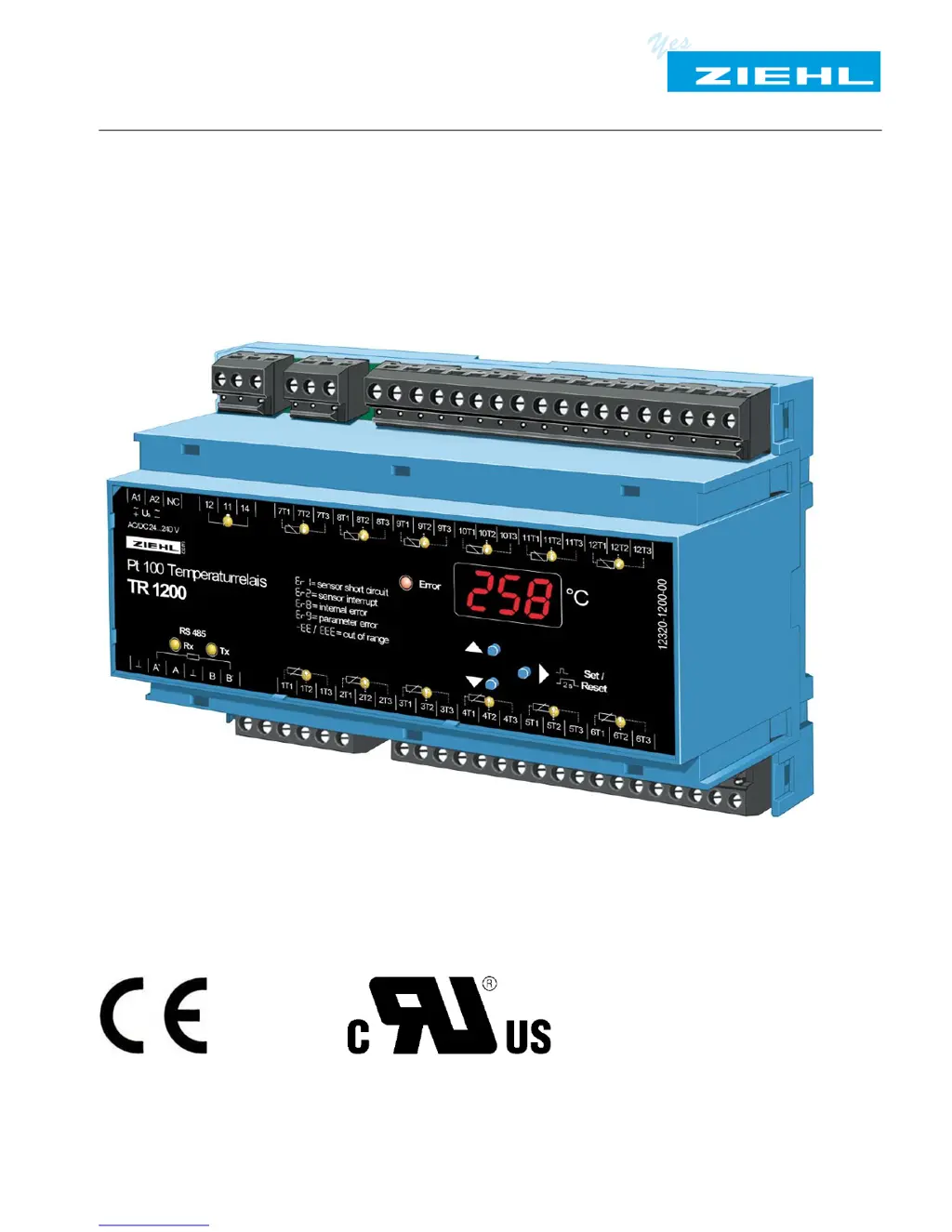
    What to do if ZIEHL TR1200 Thermostat shows error code 8Er88?
    • R
      Robert McguireAug 12, 2025
      If the ZIEHL Thermostat displays error code 8Er88, this indicates an internal device malfunction. First, switch the unit off and then back on. If the error persists, the unit needs to be returned to the factory for repair.
  • M
    Mr. Tim AlvarezAug 15, 2025
    What to do if ZIEHL Thermostat displays error code 8Er98?
    • M
      micheal19Aug 15, 2025
      If the ZIEHL Thermostat displays error code 8Er98, this indicates an invalid parameter. To resolve this, press the "SET" button for 10 seconds while switching on the supply voltage to reset to factory settings.
  • M
    Michelle SkinnerAug 23, 2025
    How to unlock parameter configuration on ZIEHL TR1200?
    • J
      Jeffrey WilsonAug 23, 2025
      If the ZIEHL Thermostat's parameter configuration is not allowed, it's likely that the code lock is active. This feature protects against settings manipulation. If you've forgotten the PIN, perform a code reset by pressing the "SET" button for 2 seconds while switching on the supply voltage. The display will cycle through 88888 – 8Cod8 – 8off8 – 88888. Release the "SET" button to set the code to OFF, with PIN = 504.
  • P
    Patrick JohnstonAug 27, 2025
    What to do if ZIEHL Thermostat displays error code 8Er18?
    • J
      Joseph MasonAug 27, 2025
      If the ZIEHL Thermostat displays error code 8Er18, it indicates a sensor or line short circuit. The error LED will illuminate, and the LED of the corresponding sensor will flash. You should check the sensors, wires, and terminals to identify and fix the short circuit.
  • R
    Robert OnealAug 30, 2025
    What to do if ZIEHL Thermostat displays error code 8Er28?
    • D
      Dr. James MorganAug 30, 2025
      If the ZIEHL Thermostat displays error code 8Er28, it indicates a sensor or line interruption. The error LED will illuminate, and the LED of the corresponding sensor will flash. Check the sensors, wires, and terminals to locate and fix the interruption.
  • R
    Roger WattsSep 3, 2025
    What does error code 8-EE8 mean on ZIEHL TR1200 Thermostat?
    • A
      Andrew YoungSep 3, 2025
      If the ZIEHL Thermostat displays error code 8-EE8, it indicates an under range condition where the resistance is between 15 and 18.39 ?. Check the sensor and line resistance compensation.
  • M
    Ms. Becky BaileySep 7, 2025
    What does error code 8EEE8 mean on ZIEHL TR1200?
    • T
      Tyler MitchellSep 7, 2025
      If the ZIEHL Thermostat displays error code 8EEE8, it indicates an over range condition where the resistance is between 390.26 and 400 ?. Check the sensor and line resistance compensation.
  • N
    nortonbobbySep 10, 2025
    Why my ZIEHL TR1200 showing wrong temperature values?
    • J
      James CabreraSep 12, 2025
      If your ZIEHL Thermostat shows wrong temperature values, it might be due to interchanged sensors using the 3-wire technique. Check the sensors, noting that terminals for sensor 1…6 are not compatible with terminals for sensor 7…12.

Summary

Application and Function Overview

1 Application and Brief Description

Details the suitability of the TR1200 for temperature monitoring.

2 Overview of Functions

Lists the key features and capabilities of the TR1200 device.

3 Display and Controls Explained

LED Indicators and Digital Display

Describes LED states for relay, sensors, RS485, and the 3-digit display.

Control Buttons and Mode Indicators

Explains the function of Up/Down, Set/Reset buttons and decimal point indicator.

4 Terminal Descriptions

Power, Relay, and Sensor Terminals

Details connection points for supply voltage, error relay, and temperature sensors.

RS485 Interface Terminals

Specifies terminals for RS485 communication, including load resistor.

5 Important Safety and Operational Notes

Hazardous Voltage Warning

Critical safety alert regarding high voltage and potential for severe injury.

Safe Usage and Qualified Personnel

Guidelines for safe operation, installation, and the need for qualified personnel.

6 Installation Procedures

Mounting and Environmental Considerations

Covers device mounting on rails and requirements for cabinet installation.

Power Supply and Protection Setup

Details universal power supply connection and circuit-breaker protection.

7 Connection Diagram

8 Commissioning Steps

8.1 Control Chart for Device Modes

Visual flowchart of device operation modes: Display, Menu, and Parameter.

8.2 Parameter Configuration

Sensor, Relay, and RS485 Settings

Configuration of sensor types, relay function, and RS485 interface parameters.

8.3 Display and Menu Mode Operations

Button Functions in Display;Menu Modes

Explains key operations for navigating and interacting with modes.

8.5 Configuration Mode Operations

Setting Parameter Values

Procedure for adjusting parameter values using Up/Down keys.

8.6 2-Wire Line Resistance Compensation

8.7 Configuring Sensors

Sensor Connection and Line Compensation Setup

Steps for configuring sensor connection types and line resistance.

8.8 Configuring the Relay

Relay Function Selection

Setting the relay to zero signal current or operating current mode.

8.9 Configuring the RS485 Interface

RS485 Protocol and Address Settings

Configuring protocol, device address, baud rate, and parity.

RS485 Address for Sensors 7-12

Note on how addresses for sensors 7-12 are assigned.

8.10 Simulation Mode

Simulating Sensor Input

Process for selecting sensors and simulating temperature values.

8.11 Code Lock Security

Activating and Managing the Code Lock

Procedure for setting up, changing, or disabling the parameter code lock.

8.12 Display Indications Reference

Error Messages and Menu Item Descriptions

Reference for error codes and menu item meanings.

9 Factory Settings and Software Version

Accessing Factory Settings and Software Version

Procedure to view factory defaults and device software version.

10 Maintenance and Repair

Maintenance-Free Operation Policy

Information on the device being maintenance-free and manufacturer repairs.

11 Troubleshooting Guide

Error Code Causes and Remedies

Table listing error codes, their causes, and recommended solutions.

Code Lock and Parameter Configuration Issues

Troubleshooting invalid parameter errors and code lock management.

12 Technical Data

Electrical and Supply Specifications

Details on voltage, current, power consumption, and UL ratings.

Temperature Measurement and Sensor Specs

Information on measuring time, range, resolution, and sensor connections.

RS485 Interface and Test Conditions

Parameters for RS485 communication and test condition ratings.

12.1 EMC and Environmental Data

EMC Test Results and Environmental Limits

Covers EMC test standards and ambient operating conditions.

Housing, Mounting, and Physical Specs

Details on housing dimensions, mounting, wire connection, and weight.

13 Housing Design V8

Detailed Housing Dimensions and Components

Provides dimensional drawings and identification of housing parts.

14 RS485 Interface Protocols

Protocol Overview and Selection

Describes supported protocols and how to select them.

14.1 Modbus Protocol Documentation

Information source for Modbus protocol details.

14.2 RS485 Protocol Details

Transmission Format and Data Structure

Details on transmission format, compatibility, and data packet composition.

Master Request and TR1200 Response Formats

Explains the structure of requests from the master and responses from the TR1200.

14.3 RS485 Data Transmission Examples

Request and Answer Data Packet Examples

Illustrates request/answer sequences with data breakdown.

Sensor Data Transmission Logic

Explains how sensor data is transmitted based on address and configuration.

15 Appendix: SIPROTEC Configuration

Configuration for Simplex Operation Mode

Steps for configuring TR1200 for Siemens SIPROTEC Simplex mode.

Configuration for Half Duplex Operation Modes

Steps for configuring TR1200 for Siemens SIPROTEC Half Duplex modes.

ZIEHL TR1200 Specifications

General IconGeneral
BrandZIEHL
ModelTR1200
CategoryThermostat
LanguageEnglish