EasyManua.ls Logo

ZIEHL TR250 User Manual

ZIEHL TR250
18 pages
To Next Page IconTo Next Page
Page #1 background imageLoading...
Page #1 background image
ZIEHL industrie elektronik GmbH + Co KG
Daimlerstr.13, 74523 Schwäbisch Hall, Germany
+ 49 791 504-0, info@ziehl.de, www.ziehl.de
Temperature Relays and MINIKA® Mains Monitoring Digital Panelmeters MINIPAN® Switching Relays and Controls Measuring Transducers Grid- and Plant Protection
Operating Manual TR250
updated: 2016-12-19/Sc
TR250 12410-0701-03 Page
1
/ 18 www.ziehl.de
- Temperature-Relay TR 250
New from firmware -01
Program Pr5 for protection of transformers with 2 PTC-circuits (sensor-alarm, pre-alarm and tripping)
Program Pr6 for Protection of transformers with 3 PTC-circuits (forced cooling, pre-alarm and tripping)
Display of firmware version: Press Set ► for 10 s (in display mode)
Question and Answer IconNeed help?

Do you have a question about the ZIEHL TR250 and is the answer not in the manual?

ZIEHL TR250 Specifications

General IconGeneral
BrandZIEHL
ModelTR250
CategoryRelays
LanguageEnglish

Summary

Display and Operating Elements

Alarm and Sensor LEDs

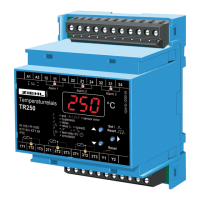
Describes the status and meaning of alarm and sensor LEDs.

Display and Buttons

Explains the 3-digit display and the function of various buttons.

Default Settings

Program Configurations (Pr1-Pr6)

Details the 6 selectable programs for various applications and their default settings.

Application and Short Description

Function Overview

Connecting Diagram

Function Diagram

Time of Response

Explains how measuring time affects response.

Relay Locked Switching

Describes the behavior of relays in locked mode.

Important Notes

Safety and Operational Precautions

Highlights dangers like hazardous voltage and general safety guidelines.

Sensor Connection and Power Supply

Specifies terminals for sensors and universal power supply details.

Installation

Mounting and Circuit Protection

Details installation in cabinets, on walls, and required circuit protection.

Putting into Operation

9.1 Display Mode

Explains how to read the display and LEDs.

9.2 Programming Mode - Sensors and Alarms

Details sensor selection, alarm limits, hysteresis, and delays.

9.3 Relay Functions and Tests

Covers relay modes, periodic testing, simulation, and code lock.

Operation

Operation with Pushbuttons

Explains navigation and control using buttons.

Configuration Flowcharts

Visual guides for sensor, alarm, and error configuration.

Error Reports Legend

Explains the meaning of various error codes.

Trouble-shooting and Remedies

Factory Presets and Firmware

Accessing factory settings and checking firmware version.

Display Errors (Sensor/Device)

Interpreting display codes for sensor and device errors.

Programming and Code Lock Issues

Troubleshooting problems with programming and code lock activation.

Temperature and Relay Operation Issues

Resolving temperature display discrepancies and unexpected relay trips.

Technical Data

Supply Voltage and Power

Details rated supply voltage, tolerance, and power consumption.

Relay Output Specifications

Lists switching voltage, current, and power ratings.

Electrical Ratings and Contacts

Covers operational current, fuse recommendations, and contact life.

Test Conditions and EMC

Outlines test conditions, insulation, and EMC test results.

Environmental Conditions

Specifies operating temperature, humidity, and vibration resistance.

Sensor Connection

Sensor Characteristics

Details resistance values for short-circuit, break, and normal operation.

Accuracy and Measuring Time

Specifies sensor accuracy and measuring time.

Housing

Mounting and Dimensions

Provides details on mounting height, dimensions, and fitting.

Protection Class and Weight

Details housing protection class and device weight.

Design V4

Mechanical Dimensions

Shows overall dimensions in mm with labeled parts.

Mounting Features

Explains snap mounting and screw fixing options.

Related product manuals