ZI
EHL industrie elektronik
GmbH
+ Co KG
Daimlerstraße 13, D
74523 Schwäbisch Hall
+ 49 791 504-0, info
@ziehl.de, www.ziehl.de
T
emperature Relays and MINI
KA
® Mains Monitoring Digital Panelmeters MINIPAN® Switching Relays and Controls Measuring Transducers
Grid- and Plant Protection
O
pera
ting
Manual
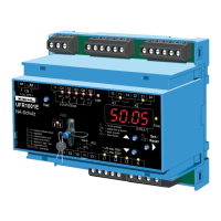
UFR1001E
updated: 2015
-11-20 Fu
from Firmware: 0-05
UFR
1001
E
12420
-0701-08
Page 1 / 45 www.ziehl.de
-
NA-p
rotection according to
VDE-AR-N 4105, in-plant power generators on the low voltage grid
- For use in in-plant power generators on the
medium voltage grid according to BDEW
- With selectable vector shift detection
- With selectable Rate of Change of Frequency (ROCOF, df/dt) protection
New, Firmware 0-05:
Default settings for
Austria
8 8 ,
Great Britain
8 8 8 8
and
monitoring of 1 or 2 phases against N
8 8
(Display of the firmware version: 8 8 8 8 for
>10s)
- Archive document -