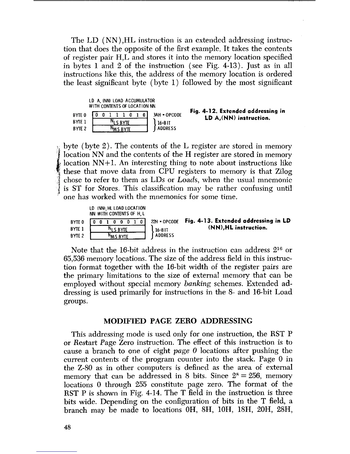
The LD (NN ),HL instruction is an extended addressing instruc-
tion that does the opposite of the first example. It takes the contents
of register pair H,L and stores it into the memory location specified
in bytes 1 and 2 of the instruction (see Fig. 4-13). Just as in all
instructions like this, the address of the memory location is ordered
the least significant byte (byte 1) followed by the most significant
BYTE 0
BYTE 1
BYTE 2
LD A, INN
) LOAD ACCUMULATOR
WITH CONTENTS OF LOCATION NN
0 0 1 1 1 0 1 0
NLS BYTE
NMS BYTE
l3AH • OPCODE
l 16-B I T
J ADDRESS
Fig. 4-12.
Extended addressing in
LD A,(NN
) instruction.
byte (byte 2). The contents of the L register are stored in memory
location NN and the contents of the H register are stored in memory
location NN+1. An interesting thing to note about instructions like
these that move data from CPU registers to memory is that Zilog
chose to refer to them as LDs or Loads, when the usual mnemonic
is ST for Stores. This classification may be rather confusing until
one has worked with the mnemonics for some time.
LD (NN
), HL LOAD LOCATION
NN WITH CONTENTS OF H,L
BYTE 0
BYTE 1
BYTE 2
0 0 1 0 0 0 1 0
NLS BYTE
NMS BYTE
22H -OPCODE
Fig. 4-13
.
Extended addressing in LD
116-BIT (NN),HL
instruction.
ADDRESS
Note that the 16-bit address in the instruction can address 216 or
65,536 memory locations. The size of the address field in this instruc-
tion format together with the 16-bit width of the register pairs are
the primary limitations to the size of external memory that can be
employed without special memory
banking
schemes. Extended ad-
dressing is used primarily for instructions in the 8- and 16-bit Load
groups.
MODIFIED PAGE ZERO ADDRESSING
This addressing mode is used only for one instruction, the RST P
or Restart Page Zero instruction. The effect of this instruction is to
cause a branch to one of eight
page 0
locations after pushing the
current contents of the program counter into the stack. Page 0 in
the Z-80 as in other computers is defined as the area of external
memory that can be addressed in 8 bits. Since 28 = 256, memory
locations 0 through 255 constitute page zero. The format of the
RST P is shown in Fig. 4-14. The T field in the instruction is three
bits wide. Depending on the configuration of bits in the T field, a
branch may be made to locations OH, 8H, 10H, 18H, 20H, 28H,
48
 Loading...