Do you have a question about the ZKTeco PB1000 Series and is the answer not in the manual?
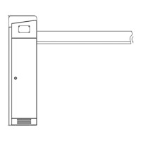
Describes the chassis appearance and dimensions for PB1000 and PB2000 series barrier gates.
Details the appearance and dimensions of different straight boom types, including 3m, 4m, and 5m options.
Lists and illustrates internal components of the barrier gate chassis, such as motor, controller, and speed reducer.
Explains the modular design and functional principles of the barrier gate's core modules.
Provides a table of specifications for different barrier gate models, including boom type, length, speed, and fastening.
Lists important safety and operational guidelines to follow during the installation process.
Outlines procedures for routing cables through protective sleeves and specifies required cable types and sleeves.
Describes marking installation positions, driving expansion bolts, and securely installing the chassis.
Details the process of assembling and attaching the boom to the barrier gate, including expansion.
Illustrates the installation layout, showing required distances between chassis, boom, and walls.
Lists essential steps and checks before performing device commissioning.
Provides step-by-step instructions for adjusting the boom's levelness and verticality.
Details optional features like cooling, heating, anti-crash, and vehicle detection.
Addresses boom response issues caused by grating malfunctions or faulty plugs.
Provides a solution for chassis vibration by tightening expansion bolts.
Lists potential causes for the boom not responding, including power, fuse, and wiring issues.
Lists specific maintenance tasks like fixing reflection film and tightening cable joints.
Defines the recommended frequency for various maintenance tasks.
Provides a detailed diagram of the control board and its connections.
Shows the main power supply and motor wiring connections.
Illustrates wiring for gratings and the PB2000 illuminator.
Shows the wiring connections for the optional loop detector.
Illustrates the wiring for the optional bumping bounce back system.
Details the wiring connections for the optional expansion board.
Shows combined wiring of the expansion board and the main controller.