2
1
360°
ca. 50%
100%
Ø
M. Züblin AG
Neue Winterthurerstr. 30
CH-8304 Wallisellen
www.zublin.ch
H
Ø *
Ø *
2,0 m 2,0 m 8 m
2,5 m 3,5 m 10 m
3,0 m 6,0 m 12 m
3,5 m 6,0 m 12 m
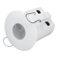
Swiss Garde 360 Presence
DALI Master A-Basic 12 m
Edition 4-2016
Master Presence detector 12 m, 360°
Master Präsenzmelder 12 m, 360°
Détecteur de présence Master 12 m, 360°
Rilevatore di presenza Master 12 m, 360°
Czujnik obecności Master o zasięgu 12 m, 360°
Hlásič přítomnosti Master 12 m, 360°
D PL
EN
I
F CZ
EN
INSTALLATION INSTRUCTIONS
1. DETECTOR
1.1 Use
The detector controls DALI units in up to three daylight zones with constant light
control based on the incoming daylight.
The detector is designed for ceiling installation in offices, schools, and public buildings.
It is equipped with a built-in light sensor as well as an IR receiver.
The communication is built on the addressable DALI principal pursuant to EN 62386-101/102.
Up to 64 DALI devices can be connected.
The detector features a built-on DALI power supply. It is therefore not necessary to connect an
external DALI power supply unit. Multiple master detectors must not be connected in parallel
because this would damage the coils and the detector.
The programming and configuring is carried out via the P-IR remote control DALI Addressable (41934).
1.2 Quick guide
Short manual for a quick configuration of the detector:
1. Install detector (3).
2. Wire the detector according to the circuit diagram. After switching on the mains voltage,
the detector is in setup mode “Out-of-the-Box” Item 1.5
3. Check the installation for errors and potentially missing light sources.
4. Initialise all DALI devices and divide the lighting in zones Item 2.2
5. Program the required functions SEMI-AUTO mode (optional, default setting AUTO mode) Item 2.6
6. Specify whether the lighting needs to be switched off in the daylights zones during illumination
(optional, default setting minimum lighting) Item 2.7
7. Configure the desired illumination level (Lux level) for the daylight zones, if it deviates from the default settings.
8. Configure the times if they deviate from the default settings Item 2.8
9. Execute a burn-in (only for fluorescent tubes) Item 2.13
1.3 Safety notes
!
Ensure that the electrical lines are de-energised before installation.
Installation is only permitted by electricians in compliance with local legislation.
1.4 Installation
Positioning
The detector responds to movements and heat in its environment. Please avoid an installation in close proximity to
stoves, electrical heaters, fans or other moveable objects because they may trigger an unintended activation (3).
Range
The installation height recommended for the detector measures 2.4–3 m. The optimal height is 2.4 m.
At this height, the detector has an effective radius of Ø 8 m (1).
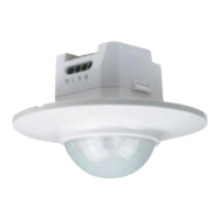
Range increase
The range of the presence detector can be increased with a slave unit (Swiss Garde 360 presence DALI Slave A-Ba-
sic). Up to 10 slave units can be connected to a master device. Using several detectors, an approximate 30% overlap
of the detection areas must be ensured for continued detection without disruptions (2).
Daylight zones
The detector controls the daylight hours, so that the whole room is illuminated with the same brightness.
As default, the zone 1 with 80%, the Zone 2 with 100% and the Zone 3 is driven with 120% illuminance
(manual fine adjustment see item 2.9)
Zone 1 always includes the devices that are closest to the daylight source (window),
Zone 2 the devices in the centre of the room and Zone 3 those that are farthest from the daylight source.
Installation
The detector is designed for flush installation on suspended ceilings.
Connection
The detector must only be connected with a voltage source after all wiring has been connected.
Wire the detector according to the circuit diagram (6).
1.5 Setup mode “Out-of-the-box”
After the detector has been connected with the voltage source and before it initialises the DALI devices,
all lights switch on and the detector operates as an On/Off detector.
All lights can be switched on and off manually via the 230 V switch for the P-IR remote control.
1.6 Default settings
After the DALI devices have been initialised, the detector operates with the following default settings:
– Function: Automatic on and off switching via the detector
– Zones: 3 daylight zones
– Illumination level: 300 lx
– Time 1 (delay): 15 min (4)
– Time 4 (standby-light): 10 min
– Min/Off: Minimum setting; during illumination, the lighting in
the daylight zones remains switched on at minimum output.
– Sensitivity: high
1.7 Operation and maintenance
Dirt accumulation impacts the function of the detector. The lenses of the detector should therefore always be kept
clean. For cleaning, use a damp cloth as well as water with a common cleaning product. Do not apply any strong
pressure on the lenses during the cleaning process. If the lenses or other components of the detector are defective,
they must be replaced.
1.8 Technical data
Supply voltage 230 V / 50 Hz
Power consumption 0,45 W
DALI devices 1–64
DALI power supply Max. 250 mA
DALI cable length Ø 2,5 mm; 2 < 300 m
Ø 1,5 mm; 2 < 150 m
Ø 1,0 mm; 2 < 100 m
Max. number of slaves 10
Detection angle 360°
Detection range max. Ø 6 m Präsenz, approx. Ø 12 m at 3 m height
Installation height 2–3,5 m
LUX setpoint 100–1000 lx
Timer control 5 min to ∞
Standby-light Off, 5 min to ∞, Level 0.1 to 51%
Protection class IP20
Temperature range -5 to +50 °C
Dimensions Ø 95x5 mm (visual dimension)
Colour RAL9010
2. P-IR REMOTE CONTROL (5)
Programming functions are entered via the P-IR remote control DALI addressable Art.-Nr. 41934.
Signalisation
– Green LED off: Detector in operating mode
– Green LED on: Detector in programming mode
Green LED flashes 1x: Command received
2.1 Lock/unlock
Press “Lock/Unlock” once to set detector to programming mode.
Press “Lock/Unlock” once to block the programming mode and switch to operating mode.
The detector must be unlocked for all configuration settings, except for “Status”, “1”, “2”, “3”, “4”, “On/Off”, “Auto”,
“Dim +” and “Dim -”. If no button is pushed for 5 min, the detector is automatically set to operating mode. Setting
changes that have already been executed will be saved.
2.2 Initialisation of the DALI devices
All DALI devices are automatically addressed with the following procedure:
1. Switch on power supply
All lights on
2. Briefly press “Lock/Unlock” button: Programming mode
3. Press “Init” button for about 4 seconds: Green and red LED flash in sequence
Automatic addressing starts
1)
Each addressed light will be switched off
Addressing is finalised when all lights are switched off
4. First light is switched on again
5. Define zone through 1, 2 or 3
2)
button
6. Press “Next” button
7. Light is switched on (continue at step 5 until all lights have been allocated to one zone)
3)
8. End addressing with “Lock/Unlock” button: Operating mode
1)
Notice: If the detector does not recognise a DALI device after 10 attempts, the red LED lights up for 1 s.
This malfunction could be caused by a wiring error or a defect on a DALI device.
No Slave devices may be connected to the DALI bus during initialisation.
2)
Notice: Zone 1 always includes the devices that are closest to the daylight source (window),
Zone 2 the devices in the centre of the room and Zone 3 those that are farthest from the daylight source.
3)
Notice: If the red LED briefly lights up during the zone allocation, it means that the light is not correctly
allocated to a zone. In this case, the allocation must be repeated.
2.3 Reallocation of a light to a different zone
The light was allocated to the wrong zone or the zone needs to be switched for another reason,
please proceed as follows:
1. Press “Lock/Unlock” button: Programming mode
2. Briefly press “Init” button, all lights switch off, with the exception of the first recognised light,
which switches on at 100% output.
3. Press the “Next” button the respective number of times until the desired light switches on with 100% output.
4. Now press “1” to allocate the light to Zone 1 or “2” or “3” to allocate the light to zone 2 or 3.
5. Press “Lock/Unlock” button: Operating mode
2.4 Motion test (1)
To check whether the detector covers the required area or is impacted by a ventilation system for example, you can
activate a test function on the detector during which the activation delay is set to 2 s. In case of no presence the light
dim to minimum level. As soon as the detector recognises an activity in the detection area, all connected devices and
lights switch on. The red and green LED flash in sequence during the test function.
Note: If the master detector is tested, all connected slave testers switch into the test mode as well. However,
theslave detectors can be excluded individually from the test mode with the help of the P-IR remote control.
The test function works as follows: Press the “Lock/Unlock” button; the green LED switches on.
Then press “Test On/Off” button; the green LED switches off again and the detector is in test mode.
To end the test mode, press “Lock/Unlock” again.
2.5 External button
In SEMI-AUTO mode it is imperative to connect the external button because the light has to be switched on via
thebutton. In AUTO mode the external button is optional because the light is switched on automatically when
aperson is detected.
The lights of all zones can be switched on and off and also be dimmed manually via the external button.
When the manual operation is active, the daylight control is deactivated:
Keep button pressed for > 1 s to undim or dim the lighting or reverse when pressing the button again.
The newly set artificial brightness level of the light remains constant but will not be saved. When the light is
switched on again, the originally set mixed light brightness level applies again.
Press and hold the button to switch the detector to the statuses “Permanent ON” and “Permanent OFF”.
The red LED lights permantently to display the statuses “Permanent ON/OFF”.
The statuses “Permanent ON” and “Permanent OFF” are cancelled before the time elapses by briefly pressing
thebutton again:
– Press the button for 0.1–1.0 s
Automatic mode (ON / OFF)
– Press and hold the button for 1.0–6.0 s
“Dim +” or “Dim -”
– Press and hold the button > 6.0 s
“Permanent ON” or “Permanent OFF”
2.6 Set AUTO / SEMI-AUTO mode
SEMI-AUTO mode: The detector only switches the lighting on if the illumination level of the switch has been activated
depending on the setting. After the expiration of a preset time that lapses after the last recorded activity, the lighting
is automatically switched off.
AUTO mode: The detector automatically switches on the lighting according to the setting of the illumination level
when an activity is registered in the detection area. After the expiration of a preset time that lapses after the last
recorded activity, the lighting is automatically switched off.
The mode is set via the P-IR remote control:
1. Briefly press “Lock/Unlock” button: Programming mode
2. Briefly press “On/Off” button
Green LED flashes: SEMI-AUTO Mode
Red and then green LED flashes: AUTO mode
3. Briefly press “Lock/Unlock” button: Operating mode
2.7 Select between minimum lighting and switching off
For the daylight zones it can be specified whether the detector needs to switch off the lights with sufficient daylight
(meaning the daylight alone is sufficient to achieve the required illumination level) or whether to switch to minimum
lighting. The setting can be carried out via the “Min/Off” button.
1. Briefly press “Lock/Unlock” button: Programming mode
2. Briefly press “Min/Off” button
Green LED flashes: Switch off lighting
Red and then green LED flashes: Minimum lighting
3. Briefly press “Lock/Unlock” button: Operating mode
Note: Minimum lighting is active during motion detection and with sufficient daylight. The standby lighting becomes
active after the expiration of Timer 1 (motion detection). When the detector job is supposed to be switched off after
the lapse of Timer 1, the standby lighting must be deactivated Item 2.10
2.8 Setting of illumination levels
The respective required value depends on the capacity of the lighting system to provide the required illumination
level. In contrast, the situation may occur that the lighting system can provide a higher illumination level than
required. The detector can control both conditions.
To set the illumination level, please proceed as follows:
1. Briefly press “Lock/Unlock” button: Programming mode
2. Briefly press “Lux” button
3. Select desired illumination level 100–1000 lx (briefly press button)
4. Briefly press “Lock/Unlock” button: Operating mode
2.9 Fine setting of the preset illumination levels
If certain zones are illuminated too strongly or not enough, fine settings can be carried out individually for each zone.
Please note, however, that these fine settings are only possible to a limited degree.
Example: If the lux meter in Zone 3 indicates insufficient illumination and if it needs to be increased, proceed as
follows: Press the “Lock/Unlock” button; the green LED switches on. Then press “Lux” and “3” to select Zone 3.
Press and hold the “Dim +” button, the green LED flashes as long as the button is pressed and the illumination in
Zone 3 increases. Finally, press “Lock/Unlock” again; the green LED switches off.
Note: The detector works on the basis of the effective daylight recording at the end of the programming process
with “Lock/Unlock”. Up to 2 minutes may pass until the change is adopted and the lighting is reset.
2.10 Time settings (4)
The following timers are available:
Time 1 (delay)
Time 4 (standby-light)
The times are set as follows:
1. Briefly press “Lock/Unlock” button: Programming mode
2. Briefly press “Time” button
3. Press button for “time”
“1”
Delay
“4”
Standby-light
4. Select desired time 5 min - 60 min (standby-light also possible without limits “∞”)
5. Briefly press “Lock/Unlock” button: Operating mode
2.11 Switch off standby-light and set level
Disable standby-light:
1. Briefly press „Lock/Unlock“: Programming mode
2. Briefly press „Time“
3. Briefly press „4“
4. Briefly press „On/Off“: Standby-light is switched on or off respectively
5. Briefly press „Lock/Unlock“: Operating mode
Standby-light level may be set from 0.1 to 51%:
1. Briefly press „Lock/Unlock“: Programming mode
2. Press „Dim+“ or „Dim-“ respectively: level is set
3. Briefly press „Lock/Unlock“: Operating mode
2.12 Setting of sensitivity (1)
The sensitivity of the detector can be set.
To do so, please proceed as follows:
1. Briefly press “Lock/Unlock” button: Programming mode
2. Briefly press “Sens” button and then “1” for maximum sensitivity,
“2” for high sensitivity, “3” for low sensitivity or “4” for minimum sensitivity.
3. Briefly press “Lock/Unlock” button: Operating mode
Example: The detector needs to work with maximum sensitivity. Press the “Lock/Unlock” button; the green LED
switches on. Then press “Sens” and “1”. Finally, press “Lock/Unlock” again; the green LED switches off.
2.13 Reset to default settings
If the detector needs to be reset to its default settings, meaning into the “Out-of-the-box” setup mode, please
proceed as follows:
1. Press “Lock/Unlock” button: Programming mode
2. Press and hold “Fact. set” button for about 4 s until the green LED switches off briefly as a confirmation.
3. Press “Lock/Unlock” button: Operating mode
The detector was reset to its default settings and must be newly set up,
which means all DALI devices must be readdressed.
2.14 Burn-in activation (100 h)
During the start-up or prior to the replacement of fluorescent tubes, a burn-in of the tubes must be carried out to
optimise the operating life. During the burn-in process, the detector operates the lights with an output of 100%.
Thedaylight control is switched off as long as the burn-in function is active and activity is registered in the detection
area. After the completion of the burn-in process, the detector automatically switches back to daylight control.
Aslong as the burn-in function is active, the lighting can neither be dimmed via the buttons nor via the P-IR remote
controls. In case of a power supply disruption, the detector saves the lapsed time of the burn-in function and the
time measurement will be continued as soon as the power supply is restored. The active burn-in process is indicated
by a yellow LED, which blinks once per second when the detector is in operating mode.
Activation of the burn-function:
1. Press “Lock/Unlock” button: Programming mode
2. Press “Burn in” button to activate or deactivate the burn-in function.
a. Green LED flashes 1x
Burn-in active
b. Green LED flashes 2x
Burn-in inactive
3. Press “Lock/Unlock” button: Operating mode
In the operating mode, the red and green LED are switched on simultaneously when the burn-in function is active.
Status display
Press “Status” to read out the status of inidvidual parameters on the detector. Parameters are displayed in operating
mode by the flashing of the green LED. If the green LED does not light up, the device is not yet initialised. Await the
flashing signal before repressing any buttons.
2.15 Status – time (4)
To read the individual times, first press “Status” and then “Time”.
Time 1 = delay, Time 4 = Standby-light.
Depending on which time needs to be applied, press “1” for Time 1 or “4” for Time 4.
The detector indicates the time respective number of blinking signals from the LED.
Time (min) 5 10 15 30 45 60 ∞ Off (only Time 4)
Number of flashing
light signals, green
1 2 3 4 5 6 7 8
Example 1: Reading of the delay time 1: Press the “Status” button, then “Time” and “1”. The green LED flashes 3
times, which means that the delay time has been set to 15 min.
2.16 Status - Illumination level
To display the programmed illumination level, first press “Status” and then “Lux”.
The detector indicates the illumination level values through a respective number of blinking signals from the LED.
Lux (lx) 100 200 300 400 600 800 1000
Illumination level
set manually
Number of flashing
light signals, green
1 2 3 4 5 6 7 8
Example: Display of the required illumination level: Press “Status” button and then “Lux”.
The green LED flashes 3 times, which means that the required illumination level has been set to 300 lx.
2.17 Status – sensitivity
To display the programmed illumination level, first press “Status” and then “Sens.”.
The detector indicates the sensitivity through a respective number of blinking signals from the LED.
Sensitivity Maximum High Low Minimum
Number of flashing
lightsignals
1 2 3 4
Example 1: Press “Status” button and then “Sens.”. The green LED flashes 2 times,
which means that a high sensitivity has been set.
2.18 Status – Burn-in
The status of the burn-in function is indicated by LED blinking signals on the detector. The number of blinking signals
of the green LED indicates the number of hours that the burn-in function remains active. However, if the red LED blinks
once, it means that the burn-in function is not active.
Press “Status” button and then “Burn in”. The detector indicates the remaining time in 10 hours intervals.
If the red LED is illuminated, the Burn-in function is inactive.
Burn-in
≤ 10 h ≤ 20 h ≤ 30 h ≤ 40 h ≤ 50 h ≤ 60 h ≤ 70 h ≤ 80 h ≤ 90 h ≤ 100 h
Number of flashing
light signals, green
1 2 3 4 5 6 7 8 9 10
Example 1: Reading of the burn-in status. Press “Status” button and then “Burn in”.
The green LED flashes twice, the remaining time of the burn-in function is 20 h.
2.19 Status - zones
Which device is allocated to which zone can be indicated by first pressing “Status” and then “1” for Zone 1, “2” for
Zone 2 or “3” for Zone 3. All devices of the selected zone switch on for 5 seconds while all others will be switched off.
After the expiration of the 5 s, all devices in all zones switch back to their original status.
Example: It needs to be determined which devices are allocated to Zone 2. Press the “Status” button and then “2” for
Zone 2. All lights allocated to Zone 2 will be switched on for 5 s with 100% output and all potential relays will also be
activated for 5 s. All other units will be switched off.
2.20 Status - minimum lighting or switch off
To determine whether the lighting switches off or switches to minimum output in the daylight zones during illumina-
tion, press the “Status” and the “Min/Off” button. The red LED on the detector blinks when the device is switched to
minimum output or the green LED flashes when the lighting is switched off.
Example: Display of the setting of the lighting in the daylight zones during illumination. Press “Status” button and
then “Min/Off”. A red LED blinks on the detector which means that the lighting in the daylight zone remains switched
on during the illumination at minimum output.
2.21 Status - AUTO or SEMI-AUTO functions with automatic switch off
To display the setting, press the “Status” button and then “On/Off”. If the red LED blinks on the detector,
the AUTO function is active via the detector. The green LED flashes, the SEMI-AUTO function is active with
automatic switch off via the detector.
Example 1: Press “Status” button and then “On/Off”. The red LED on the detector blinks once, which means that
Zone 1 has been programmed for AUTO.
2.22 Switch all zones on and off
With the “On/Off” button, all zones can be switched on and off.
2.23. Dim all zones
With the “Dim +” of “Dim -” buttons, the lighting in those zones can be amplified or reduced.
“Dim +” or “Dim -” must be pressed until the desired lighting level has been reached. Then release the button.
Aslong as one of the buttons is pressed, the green LED flashes.
2.24 Switching on/off and dimming certain zones
Instead of maintaining control of all zones, they can also be individually selected and individually controlled.
To do so, first select the desired zone: Press “1” for Zone 1, “2” for Zone 2 or “3” for Zone 3, then the function
buttons “On/Off” or “Dim +” or. “Dim -”. After selecting the zone, e.g. button “1”, the function button must be pressed
within 4 s.
Example 1: Switching Zone 1 on and off. Press button “1” and then “On/Off”.
The detector activates the daylight control and switches all devices in Zone 1 either on or off.
To reactivate the automatic daylight control, press “Auto”.
Example 2: The lights in Zone 2 need to be dimmed. Press button “2” and then “Dim -”.
The daylight control is deactivated and the lights in Zone 2 are dimmed as long as the “Dim -” button is kept pressed
and the green LED flashes. Release the button when the desired illumination level has been reached, the green LED
does not blink any more.
To reactivate the automatic daylight control, press “Auto”.
Note: When you have selected a zone, e.g. “1” for Zone 1, and a function, e.g. “On/Off”, but you want to activate a
different function, please wait 4 s and then select a different function. During this time Zone 1 remains activated.
3. LED status display
Status Display
“Out-of-the-box” The detector is connected but not yet initialised.
Unlock The green LED lights up while the detector is programmed and
ready for setup via the P-IR remote control.
Lock The green LED switches off. The programming mode of the detector is completed and all
executed changes are saved.
Zone allocation The green LED briefly switches off when a correct selection has been made.
When the green LED switches off for 1 s and the red LED switches on for 1 s,
the allocation of the device to a zone was unsuccessful.
Test mode The green and red LED flash in sequence.
P-IR remote control
(accessories)
Each time when the detector receives a signal confirmed via the P-IR remote control,
it is confirmed by a brief switch off of the green LED when it is in programming mode.
If it is in operating mode, the green LED flashes briefly.
Dim + The green LED blinks as long as the button is pressed.
Dim - The green LED blinks as long as the button is pressed.
Burn-in
When the function is active,
the red and the green LED are switched on continuously.
The crossed-out wheeled dust bin symbol indicates that products must be
collected and disposed of separately from household waste. Use an official
collecting point or contact your retailer where the product was purchased.