40
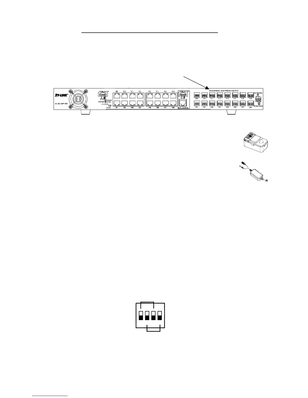
Chapter 7 Brightness / Sharpness (Colour) Control Switch Settings
7.1 Control Switch Settings on the following Mixer models for transmission distance
up to 500m. (1,640 ft.)
Push-Fit Mixers:
- PF068A12 Universal Mixer for up to 500m, DC 12V 680mA to camera
- PF068A24 Universal Mixer for up to 500m, AC/DC 24V 340mA to camera
Pig-Tail Mixers
- PT068A12 Universal Mixer for up to 500m, DC 12V 680mA to camera)
7.1.1 For wire length of less than 250 m (825 ft.) – (between the Mixer and Signal
Processor)
The built-in automatic alignment circuitry is designed to provide the optimal high quality
images in terms of Brightness and Sharpness (Colour) with all four Control Switches (Dip
Switches) put to “LOWER” positions (ex-factory setting), as shown in Fig. 7.1.1.1.
Therefore, no switch adjustment is required for wire length of less than 250 m (825 ft.) when
this Signal Processor is with ex-factory setting and used with Mixer Models listed under
paragraph 7.1.
UPPER Position ----->
LOWER Position --->
Fig. 7.1.1.1
SHARPNESS
BRIGHTNESS
ON
4
32
1
Brightness/Sharpness Control Switch