EasyManua.ls Logo

3Com SuperStack II Hub 10 User Manual

3Com SuperStack II Hub 10
8 pages
To Next Page IconTo Next Page
Page #1 background imageLoading...
Page #1 background image
Related Standards
The Hub 10 Telco has been designed to conform to the following
standards:
Physical
Electrical
Hub 10 Telco only
Hub 10 Telco & Management Module
Environmental
T
ECHNICAL
I
NFORMATION
Functional
ISO 8802/3, IEEE 802.3
Safety
UL 1950, EN 60950, CSA 22.2 #950
EMC
EN 55022 Class B, EN 50082-1, FCC Part 15 Class A,
CSA C108.8 Class A
(screened cables must be used to ensure
compliance with these standards)
Environmental
EN 60068 (IEC 68)
Width
440mm (17.3 ins)
Depth
224mm (8.8 ins)
Height
44mm (1.7 ins) or 1U
Weight
2.6kg (5.7lb)
Mounting
free standing,
or 19" rack or wall mounted using kit supplied
Power Inlet
IEC 320
Fuse Protection
2 Amps
Power Consumption
22 VA
Power Dissipation
73 BTU/hr
Power Inlet
IEC 320
Fuse Protection
2 Amps
Power Consumption
30 VA
Power Dissipation
100 BTU/hr
Operating Temperature
0-50°C (32-122°F)
Humidity
0-90% (non-condensing)
SuperStack™ II Hub 10
Telco (3C16672A)
User Guide
DUA1667-2AAA03
Question and Answer IconNeed help?

Do you have a question about the 3Com SuperStack II Hub 10 and is the answer not in the manual?
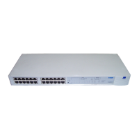
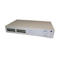
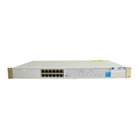
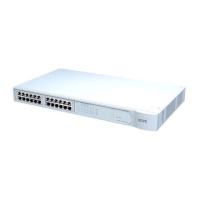
3Com SuperStack II Hub 10 Specifications

General IconGeneral
Ports12 x 10Base-T
Data Rate10 Mbps
Power SupplyInternal
Data Transfer Rate10 Mbps
Data Link ProtocolEthernet
Compliant StandardsIEEE 802.3
ModelSuperStack II Hub 10
Status IndicatorsPower
Port TypeRJ-45

Summary

TECHNICAL INFORMATION

Safety

Details safety compliance standards like UL 1950 and EN 60950.

EMC

Covers Electromagnetic Compatibility standards like EN 55022 Class B.

Electrical

Provides electrical specifications for the Hub 10 Telco.

Hub 10 Telco & Management Module

Details electrical specs for the unit with management module.

Safety INFORMATION

INTRODUCTION

Management

Explains management options with modules.

Resilience and Security

Details features for resilience and security.

Front Panel

MDI Switch

Explains the function and settings of the MDI switch.

STATUS LEDs

Details the meaning and troubleshooting for STATUS LEDs.

TCVR LED

Explains the TCVR LED status and potential causes for partitioning.

Power LED

Details the Power LED status and troubleshooting steps.

Rear Panel Connection

Power Supply and Fuse

Details power supply requirements and fuse replacement.

Disable On Boot Switch

Details the function and use of the Disable On Boot switch.

Power Up

RACK MOUNTING KIT INSTRUCTIONS

Related product manuals