3DGence DOUBLE P255 - maintenance activities | version 07.2021
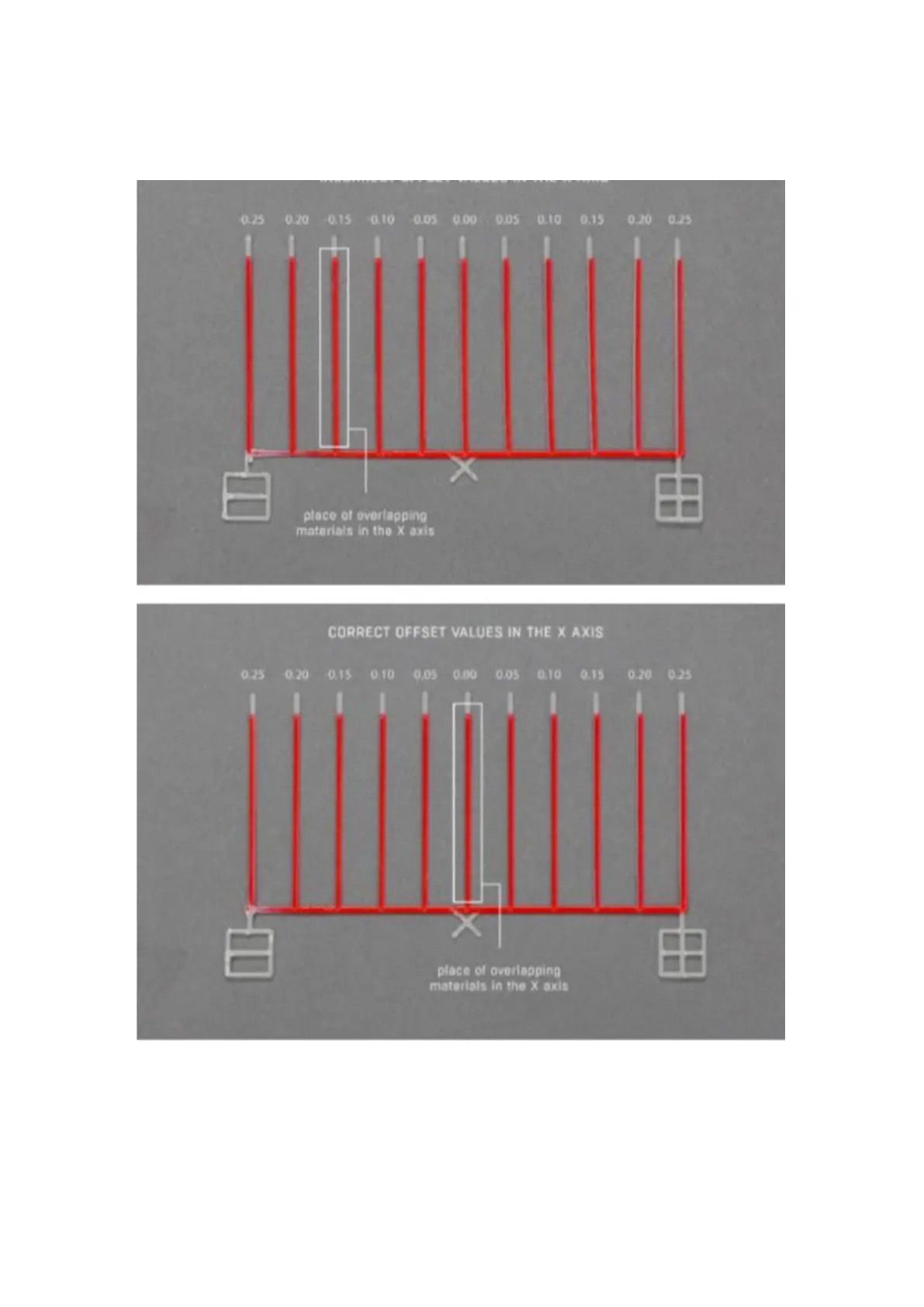
First of all, on the out of calibrated model find the line on which the model material (fig. 64, red) is best covered with
support material (fig. 64, white). On the top model (fig. 64), the materials overlap best on the third line to the left of
point 0.00. This line is distanced from point 0.00 at -0.15mm. This means that the X offset value is shifted by -0.15
mm and by this value the X offset value entered in the calibration menu must be corrected (the offset procedure in
the X and Y axis is described below).
Fig. 64 Comparison of correctly calibrated offset values with incorrectly calibrated ones