Do you have a question about the 3DGence INDUSTRY F340 and is the answer not in the manual?
Overview of the manual's purpose and the 3DGence INDUSTRY F340 printer.
Explains FFF technology and the 1.75mm filament used by the 3DGence INDUSTRY F340 printer.
Details hazard warning signs, focusing on temperature warnings, auxiliary symbols, and the emergency stop button.
General safety guidelines, prohibitions, installation requirements, carrying, connection specs, and pre-startup checks.
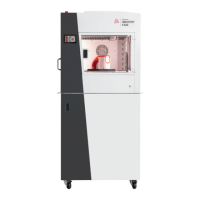
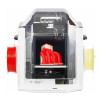
Details the main components of the printer, including outline, kinematic system, bed, chambers, heads, and power.
Lists the consumables and accessories included with the 3DGence INDUSTRY F340 printer.
Describes the touch screen interface, standby menu, and menus during operation.
Instructions for installing the 3DGence Slicer software and updating firmware.
Steps for unpacking, positioning, and safely powering on the printer.
Instructions for cleaning and calibrating the working table for optimal print adhesion.
Procedures for installing and removing filament using the Smart Material Manager system.
Instructions on how to start a print from an SD card using pre-loaded machine codes.
Guidelines for evaluating the first print, focusing on model base, seam, geometry, and walls.
Procedures for safely removing printed models from the working table after cooling.
Details the SMM system for material loading, monitoring, and error handling.
Instructions for cleaning hotends and the heatbed after printing.
Explains the printer's sleep mode for reduced power consumption and how to configure it.
Safely turns off the printer by using switches, allowing for cooling and disconnecting power.
Introduces the 3DGence Slicer software for preparing machine codes and its support.
Explains the producer's guarantee for model quality with dedicated software and materials.
Details software download, recommended hardware requirements, and update consent.
A step-by-step guide to loading, arranging, selecting, and preparing models for printing.
Overview of the 3DGence Slicer interface, including model control, status bar, and workspace.
Displays model details (name, quantity, volume) and software status.
Reverts recent model operations or returns to the main interface from .gcode preview.
Graphic representation of the printer's workspace, highlighting printable areas.
Enables selection of the machine and its appropriate print settings.
Selects machine work mode and material.
Allows changing settings related to the visual quality of printed models.
Enables changing settings related to the durability of printed models.
Quick access to advanced options like model size offsets, overhang angle, and cooling.
Graphic representation of the loaded model for selection and modification.
The area where models can be arranged for printing.
Indicates the front of the printer and operator panel.
Displays the virtual printer axes.
Initiates machine path calculation (g-code generation) for print settings.
Allows previewing print paths, verifying settings, and saving the .gcode file.
Identical options to those in the main software interface.
Slider to preview any layer of the active model.
Returns to the main interface from preview mode, allowing edits.
Previews printout paths, mesh, and tool paths; shows model and support color coding.
Displays information like model name, volume, duration, and material consumption.
Saves the model as a gcode executable file with user-specified location and name.
Accesses custom profiles, highlights hazards, and allows loading advanced options.
Window to modify custom profile settings like layer height, line width, etc.
Allows sharing print profiles with the producer for certification or updates.
Guides users through selecting, warning confirmation, and importing custom profiles.
Explains the replaceable dual-head module, its parts, and functionality.
Provides instructions and cautions for installing and replacing the dual-head module.
Explains bed scanning for autocalibration and single-point measurement for autocompensation.
Lists symptoms indicating when heatbed calibration is necessary.
Describes precision axes alignment for dimensional correction using calibration prints.
Calibrating XY offsets using a test print and measuring rifts between materials.
Troubleshooting force sensor errors related to the printing module.
Addresses Z-axis endstop issues, including distance measurements and force sensor checks.
Troubleshooting temperature sensor errors for heating devices.
Addresses Z-axis minimum endstop issues and distance checks.
Troubleshooting errors related to measurement accuracy and force sensor readings.
Troubleshooting extrusion quality coefficient errors.
Troubleshooting communication errors with extrusion quality sensors.
Troubleshooting reading errors for extrusion quality sensor position.
Troubleshooting issues with extrusion quality sensor magnetic elements.
Troubleshooting communication errors with the printing module strain gauge.
Troubleshooting communication errors with the feed material weight sensor.
Troubleshooting communication errors with the NFC reader.
Troubleshooting communication errors with the printing module's memory.
Troubleshooting communication errors with the printer's LCD operating panel.
Troubleshooting display errors of the LCD operating panel driver.
Explains ABS material properties, usage, and operating temperatures.
Defines print adhesion to the bed and factors affecting it.
Describes the printer's automated bed calibration process.
Explains single-point measurement for determining print start distance.
Defines a model part printed in the air and the need for support structures.
Describes a method for improving print adhesion by adding extra layers.
Defines CAD and its use in creating 3D models for printing.
Explains curling phenomenon and methods to prevent it.
Describes the process of generating printer paths (g-code) from a 3D model.
Defines the nozzle, its function, and impact on print quality.
Defines the extruder, its function in FFF technology, and Bowden type.
Explains optoelectronic switches that limit printer movement.
Defines filament material, parameters, storage, and SMM system usage.
Explains internal printer software responsible for interpreting commands.
Defines G-code as a programming language for CAM machines, generated by slicers.
Explains motor skipping steps due to abnormal conditions and its visual effects.
Defines HIPS as a material used for support structures for ABS.
Defines a vector normal to a plane in 3D modeling.
Describes Nylon as a polyamide material for 3D prints, with high strength.
Defines OBJ file format, its contents, and use with 3DGence Slicer.
Defines PLA as an eco-friendly material for FFF technology printing.
Defines overhangs in model parts and how slicer software generates supports.
Describes PVA as a water-soluble polymer for support structures in dual-material printing.
Describes raft as a method for enhancing print adhesion to the working table.
Defines stepper motors and their role in precise position control for the printer.
Describes skirt as initial material printed around the model for initialization.
Defines support structures generated by slicer software to hold suspended model parts.
Defines STL file format, its basic structure, and use.
Defines the extruder part responsible for feeding filament to the nozzle.
Explains warping phenomenon and methods to prevent it.
| Nozzle Temperature | up to 300 °C |
|---|---|
| Heated Bed Temperature | up to 120 °C |
| Print Speed | Up to 100 mm/s |
| Filament Diameter | 1.75 mm |
| Chamber Temperature | up to 60 °C |
| Technology | FDM |
| Nozzle Diameter | 0.4 mm |
| Supported Materials | PLA, ABS, PETG, TPU, Nylon |
| Connectivity | USB, Ethernet |
| Power Supply | 100-240V |