3
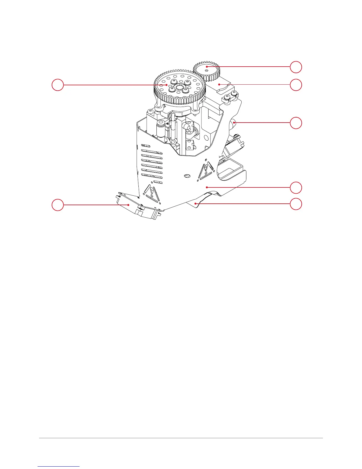
Fig. 20. Dual-head module (general view):
1. Gear wheel mechanism revolver | 2. Printout cooling fan
3. Gear wheel | 4. Servomechanism | 5. Positioning pin
6. Dual-head module cover | 7. Mechanical nozzle lock
1
2
4
5
6
7
1.7. Power supply management
1.7.1. Master switch
The printer master switch is located at the back of the device and works as a surge protector.
1.7.2. Printer power switch
The main utility printer power switch is located in the front right bottom corner of the device (g. 21).
Turning on the printer power initializes its display, turns the working area lighting and sets the T0 head in its working po-
sition. Once the work is nished and the device is cooled down, it can be used to turn the device off. For more information
on how to start the printer refer to chapter Preparing for operation, section 2.
CAUTION: if the printer does not respond to printer power switch it may mean that the emergency stop button is activated.