38 | 3DGence INDUSTRY F340
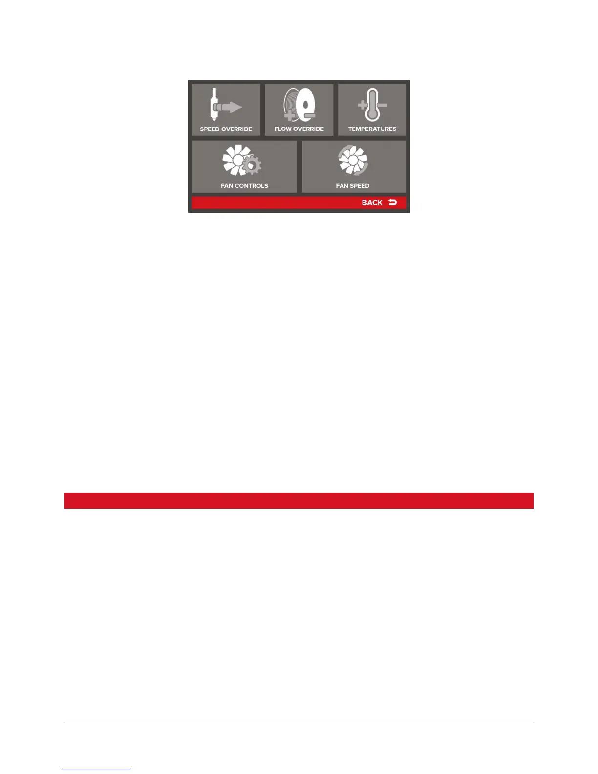
Speed Override – makes it possible to change a printing speed. It means increasing the speed of material feed and the
movements performed by the device. It does not affect e.g. the layer height. Increasing the print speed may have a neg-
ative impact on print quality. If speed is increased signicantly, it is recommended to slightly increase the temperature
of material extrusion (~ 5°C).
Flow Override – makes it possible to change the quantity of material fed. Increasing the value results in raising the rate of
feeding material to the head, at the same time there is no change to the speed of its movement. Decreasing will have the
opposite effect. The nominal value is 100% – it denes the rate of feeding material to the head resulting from the machine
code. An indication to modify the parameter could be typical failures detected during print, described in more detail in
FIRST PRINT CHAPTER, section 2.
Temperatures – the option allows users to edit temperatures during operation. When changing temperatures for heads T0
and T1 it should be noted that after changing the head, the system restores the temperature resulting from the machine
code settings (tab Toolchange Script of the Scripts panel – see SOFTWARE). Apart from heads, users can also edit the
temperature of printing bed and working chamber.
Fan Controls – settings of print cooling fans.
Fan Override – enabling this option (ON) sets the fans to power values preset in the printer. The commands resulting from
the machine code will be ignored.
Fan Enabled/Disabled – selecting this option stops the print cooling fans. No command regarding the behavior of print
cooling fans included in the machine code will be applied when this command is enabled.
Fan Speed – allows for variable adjustment of current power levels of the print cooling fans.
Increasing the power of fans can result in cracks forming in the prints – avoid excessive print cooling. The power of fans
should be increased when very small items are printed or when curling of the print edges was observed.
4. MENU STRUCTURE
Below we present a hierarchical menu structure and the description of each of its features. The menu varies depending
on the fact if the printer is operating or not. The Menu Structure for the printer is as follows:
Menu in idle status is presented in fragments due to multiple options of the interface. In sequence, the following menus
are presented:
• MAIN
• TUNE
• CALIBRATION
• CONFIGURATION
PRINT and PREPARE menus are illustrated in MAIN menu schematic diagram – they include only commands with no reference
to successive screens.
Commands are marked in bright red – using one of this eld triggers a specic printer response. Selecting white elds leads
to subsequent menu levels.