74 | 3DGence INDUSTRY F340
3DGence INDUSTRY F340 | 74
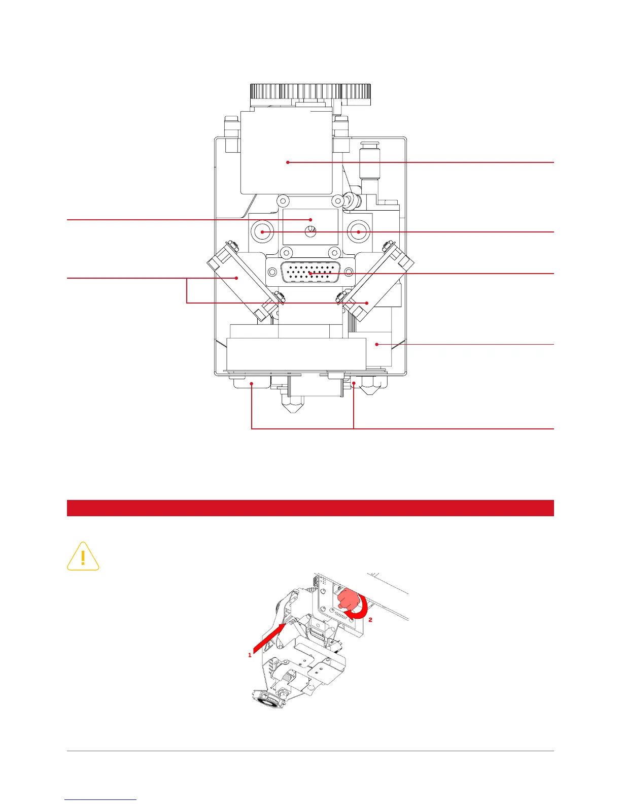
servomechanism
positioning pins
module’s connector
inactive hotend
mechanical nozzle’s blockade
cooling fans
threaded mounting hole
Fig. 36. Dual-head module, back side.
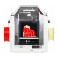
2. UNIT INSTALLATION AND REPLACEMENT
CAUTION: the module must not be installed or removed from the device while the power is on! It may result in
damage to the printer.
Fig. 37. Schematic diagram of the printing module.