When connecting the PV-Module make sure to cover it from incident sun light. Double check the PV-
exceed the maximum permissible input current of the Charge Controller (please refer to Module will not
the section Technical Date). Connect the solar module connection cable to the correct polarity of the left
pair of terminals on the solar charge controller (with the solar module symbol).
We strongly recommend connecting a fuse directly to the battery terminal to protect from any short ciruct
circuit. PV-modules generate current whenever light shines on them. The generated currentin the battery
is directly proportional to the light intensity. Even low levels of light, will deliver the PV-Modules no load,
protect PV-modules from any incident light during installation; full voltage. It is thus utterly advisable to
insulated tools, and make sure that the wire cross Never touch uninsulated cables(ends),only use electric
section is adequate for the PV module operating currents. Connections conducted in the must always be
Connect the battery cable to the two terminals in the middle of the controller with the correct polarity
Warning: High pressure danger! Solar cell modules may produce a high open circuit voltage,
to disconnect the circuit breaker or fuse before wiring, the wiring process must be careful.
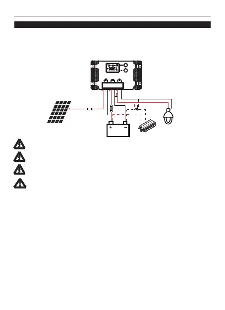
4. Conection and grounding
4.1 Conection
WARNING: Risk of explosion! In case the battery's positive and negative terminals or leads
get ever in touch, i.e. short-circuited, a fire or explosion hazard might get triggered.
Always pay maximum when handling batteries and related circuits.
CAUTION:
2.If a power inverter is used the system, it should be connected to the battery
via a DC relay. Do not connect it to the controller's load terminals.
1.Should the temperature sensor be short-circuited or damaged, the controller
can charge or discharge the battery at the default 25 ºC.
1st step: Connect loads
charge controller(with the lamp symbol). To avoid the presence of any tension on the cable/wires, please
Connect the load cable with the correct polarity of the right-hand side pair of terminals on the solar
before connecting them to the charge controller.connect these first to the load
2nd step: Connect the battery
(the controller is marked with the battery icon).
1)Should your system be nominal 12 Vdc, make sure the battery voltage is between the 10.0and 15.0 Vdc
2)For 24 Vdc nominal voltage, the battery voltage should be within the 20.0 to 30.0 Vdc range;
If the polarity is correct, the LCD on the controller will begin to display those.
3rd step: Connect the solar module
4th step: Final work
Tighten all cables connected to the controller and remove all the remains around the controller (leaving
avoid of minimum 15 cm).
4.2 Grounding
Be aware that the positive terminals of controller are interconnected and therefore bear the same electrica
potentia. If anyl grounding is required, always do this on the positive wires/terminals.
Solar charge controller MAX series User Manual
Page 2 of 10 pages
⑤
⑥
①
②
③
④
Inverter
Relay
sequence as described below.
voltage range;
The load end is prohibited from accessing the inductive load.
 Loading...