During the Backscatter (uplink) portion of the tag communication cycle, the
Receiver down-converts the modulation data from the tag to baseband, where
it is amplified and low pass filtered before being converted to a digital signal
by the ADC converter. The receiver low pass filter bandwidth is 1.4 MHz.
The receiver accommodates tag Backscatter data rates range from 32 to 640
kbps, depending on tag type and reader operating mode.
The Synthesizer section contains a voltage-controlled oscillator (VCO) and
phase-locked loop. The Synthesizer generates a Local Oscillator (LO) signal
that is shared with the Transmitter and Receiver sections. The VCO
operating frequency is constrained under software control to the 902 MHz to
907,5 MHz and 915 MHz to 928 MHz when configured for the Brazil Anatel
band.
The Digital Modem includes the DSP, FPGA, dual-function ADC-DAC
converter, and general purpose input/output communication interfaces. The
Digital Modem has direct control over transceiver functions, including
operating frequency, TX power control, and generation and decoding of
baseband digital modulation data sent and received by the reader for RFID tag
read and write operations.
4
3M Compact RFID
Reader
1000
FCC
Frequency
Hopping
Description
4.1.
Frequency Hopping
Set
The reader can be configured to operate in one of four frequency band sets,
as shown in the following table.
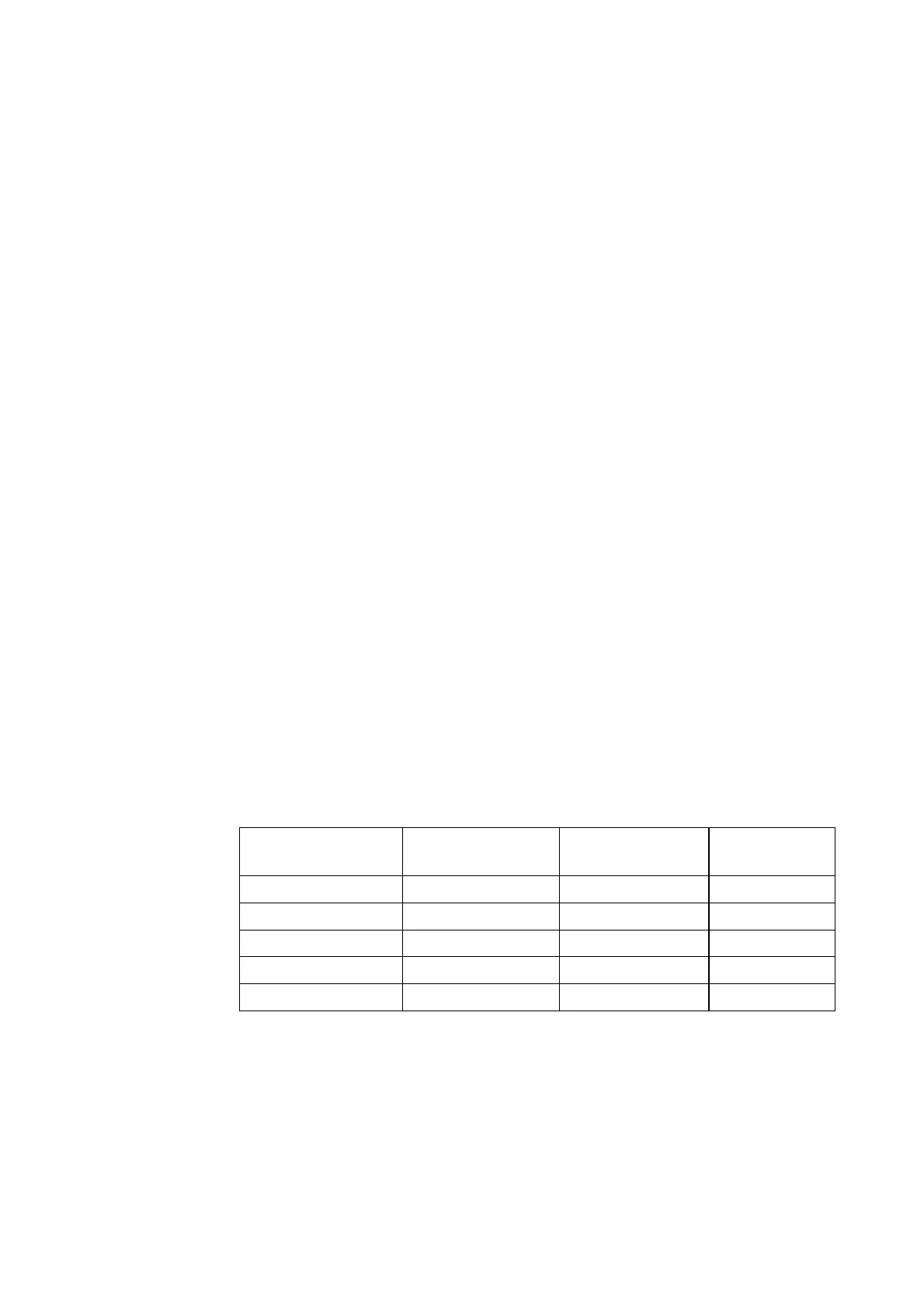
Table 1 FCC Band Specifications
Frequency Band Set Frequency Range
(MHz, inclusive)
Channel Spacing
(kHz)
No. of Channels
FCC_A 902.3 – 912.1 200 50
FCC_B 910.1 – 919.9 200 50
FCC_C 917.9 – 927.7 200 50
FCC_DENSE 902.75 – 927.25 500 50
Brazil_Band 902-907,5 / 915-918
500 50
These band sets are specified using the user-configurable Sub-Region software
setting. A pseudo random hop frequency table is created when the Sub-Region
setting is selected. The reader hops from one frequency to another in the table
at the dwell times described below in the “Timing Considerations” subsection.