36 EX II Serial Controllers Reference Guide
3M Touch Systems Proprietary Information
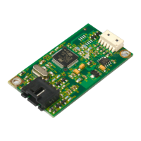
Female Connector on the Touch Screen Cable
The touch screen cable has a 12-pin (2 x 6) dual row female connector that plugs into the
controller. Table 11 describes the pins on this connector. The touch screen connector
always exits towards the serial cable.
Table 11 Touch Screen Cable Connector for EX II 17xxSC Controllers
Pin Wire Color Description
1 ——— NOVRAM interface
2 ——— NOVRAM interface
3 ——— NOVRAM interface
4 ——— +5 VDC
5
6
7
Gray
Green
Orange
Power supply ground
Chassis (earth) ground
+12V input
8 Brown Cable
shield/drain wire
Connects to the flex tail shield, which must not be grounded because the EX II
17xxSC drives the flex tail shield with an AC waveform.
9
10
11
12
White
Red
Black
Blue
Upper right (UR) corner
Lower right (LR) corner
Upper left (UL) corner
Lower left (LL) corner
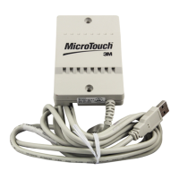
Communication Connector
All EX II 17xxSC controllers have an attached RS-232 communication cable with a 9-pin
D female connector. Table 12 describes the pins for this cable, which connects to a serial
communication (COM) port on the PC. A 9-pin to 25-pin adapter is available.
Table 12 COM Connector for EX II 1700SC Controllers
9-pin D 7-pin Molex Wire Color Description
1 No
connection
——— Data Carrier Detect (DCD).
Connected to DTR and DSR.
2 2 Brown Transmit Data (TXD). Pin 2 is the
controller’s output to the host.
3 3 Red Receive Data (RXD). Pin 3 is the
controller’s receive from the host.
4 No
connection
——— Data Terminal Ready (DTR).
Connected to DSR and DCD.
5 5 Blue Power supply ground.
6 No
connection
——— Data Set Ready (DSR).
Connected to DTR and DCD.
7 1 Black Request To Send (RTS).
Connected to CTS.
8 4 Green Clear To Send (CTS).
Connected to RTS.
9 Not used
Sleeve 6 White DC power jack (+5 VDC).
Pin 7 ——— Cable shield connected to ground.
DC power jack (ground).
Shell 7 ——— Chassis (earth) ground.
 Loading...