1. Disconnect and Remove the XT-1 Basestation off the wall
To remove the base station cover:
· Disconnect power from the base station.
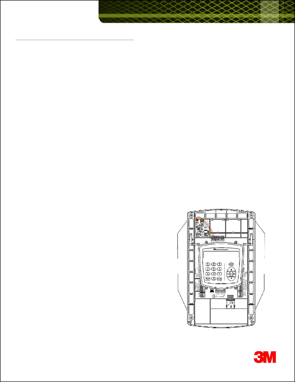
· Loosen the two screws located at the bottom of the cover.
· Lift the cover upward and away. The display and keypad remain with the base, not with the cover.
Disconnect wires terminating on XT-1 basestation
· Disconnect one wires, one at a time, from the phoenix connectors on the XT-1 basestation.
- Make sure you label each wire so you know what terminal they connect to.
For example: MEN SKR +, or MEN SKR -, or GND or MIC+ or MIC- etc
This should not be required if you have employed 3Ms guidelines on properly terminating color coded cables to
terminals on the XT-1 Basestation.
Blue & White -> Order Point Speaker
Red & Black +Shield -> Order Point Microphone + GND
Green & Yellow -> Loop terminals on Vehicle Detector board (If using Internal Vehicle Detector)
Disconnect any Range Extenders
· Disconnect one any Omni-Directional or Patch antennas connected to the XT-1 Basestation
Disconnect any external Momentary Closed Switches they may have installed to change Order Taking Modes,
SPLIT/CROSS, or DAY/NIGHT
· Most often these external switches are labeled (on the wall). It is important that while re
wiring, the same functionality (re
· Most often these external switches are labeled (on the wall). It is important that while re
wiring, the same functionality (re
to each switch) is maintained.
Remove the XT-1 basestation off the wall
· Detach the XT-1 basestation off the wall by removing the 4 screws.
· Set XT-1 basestation aside.
Screws Screws
3