7
ADF FUNCTION
On/Off
To activate the welding filter, press the ON button. After each short press of the ON button, the current settings
(shade and sensitivity) are displayed by flashing LED’s. The welding filter automatically switches off
approximately 60 minutes after the last welding arc is detected. The welding filter can also be switched off
manually by pressing the ON button for a few seconds.
Shade Selection
Three different shade settings are available in the dark state, 10, 11 and 12. In order to see the current ADF shade
setting, momentarily press the Shade button. To select another shade, press the Shade button again while the LED
is flashing, and then keep pressing the button until the LED shows the desired shade. Use the appropriate shade
for the type of welding to be performed as recommended by ANSI Standard Z49.1-1999. (Table 1)
Sensitivity Selection
Press the sensitivity button once to show the current sensitivity setting on the LED scale. Continue pressing the
sensitivity button to switch between high and low sensitivity. The sensitivity adjustment controls the amount of
light needed to trigger the ADF to the selected dark shade. In order to find a suitable sensitivity setting, start on
LOW. This setting is suitable for most applications. If the filter does not darken during welding as desired, change
the sensitivity to HIGH. If more than one person is welding in an area, “false triggering” may occur when the light
from one welder's arc triggers the filter of another welder. If false triggering cannot be solved by changing
sensitivity, the 3M™ ADF WS-020/37156 may not be suitable for the application.
LOW: Normal position. Used for most types of welding indoors and outdoors.
HIGH: Position for welding with low current or stable arcs. (e.g. TIG welding at low amps).
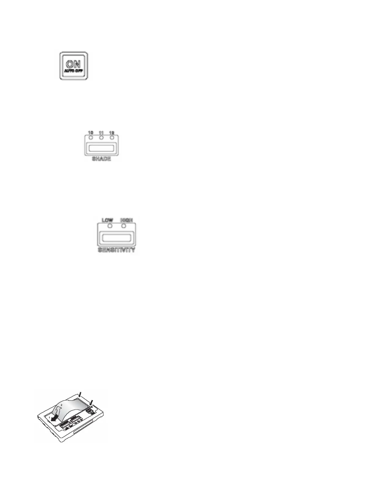
Replacement of 3M™ Inside Protection Plate WS-363/37165 (Fig. 9)
Remove the inside protection plate as illustrated. (Fig. 9) The new inside protection plate is assembled after the
protective film is removed. Insert one side under the corner retainers. Bend the middle part as necessary to insert
the other side.
Fig. 9