QSG-002 / 01-03-2017
11
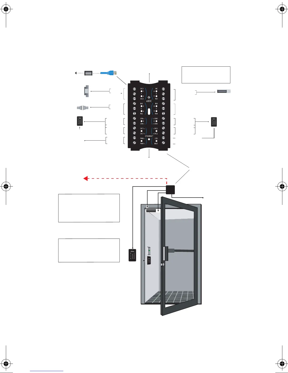
WIRE THE eIDC DOOR COMPONENTS
Up to 750 mA of power is provided through the eIDC for peripheral
devices. Figure 2 illustrates how to wire the eIDC for a single door.
Figure 2. eIDC Wiring for a Single Door
Built-in
Warning Buzzer
CAT 5/6
eIDC
To Ethernet Hub
Electro-magnetic
Lock
Door Strike
Door Contact
Card Reader
or Keypad
Card Reader
or Keypad
Built-in
Warning Buzzer
Built-in
Infrared Tamper
To Ethernet Hub
Optional
PCON
Power Connector
Ethernet
Connection
Output 1
Output 2
Input 1
Input 2
Common
Card Reader
IN
Power
Output 1
24V DC IN
Optional External
Power Supply
24 vDC, 1 Amp
Output 3 - NC
Output 3 - NO
Common
Input 3
Input 4
Common
Card Reader
OUT
Power
Output 2
Reader LED Output
Reader Buzzer Output
To Reader LED Output
Note: Maglock is required
to have additional external
power supply.
Note: The eIDC device and its
UL listed Power Supply must be
installed within the protected area
(locked area) of the access facility
to meet UL requirements.
Note: To meet UL requirements,
listed panic hardware must be
used to allow emergency exit from
the protected area.
eIDC Quick Start Guide.book Page 11 Monday, May 11, 2009 11:41 AM
 Loading...