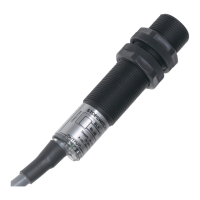
M100 Shown on Optional Whirligig®
Shaft Sensor Mount with Mag-Con™
Magnetic Connector
Fasten the M100 to a suitable mounting bracket, such as 4B’s Whirligig® universal shaft sensor mount,
with the nose of the switch within the sensing range of the target, as shown below -
WARNING
O.S.H.A. requires that all exposed rotating shafts are provided with a full guard. Therefore, this device
and its target must be equipped with a guard.
PAGE 8
STANDARD WIRING DIAGRAM
All wiring must be In accordance with local and national electrical codes and should be undertaken by an
experienced and qualied electrician.
Use dust/liquid tight exible metal conduit (when appropriate) with approved ttings to protect the sensor
cables. Use rigid metal conduit to protect the cables from the sensors to the control unit. Conduit systems
can channel water due to ingress and condensation directly to sensors and sensor connections which
over time will adversely affect the performance of the system. As such, the installation of low point conduit
drains is recommended for all sensors.
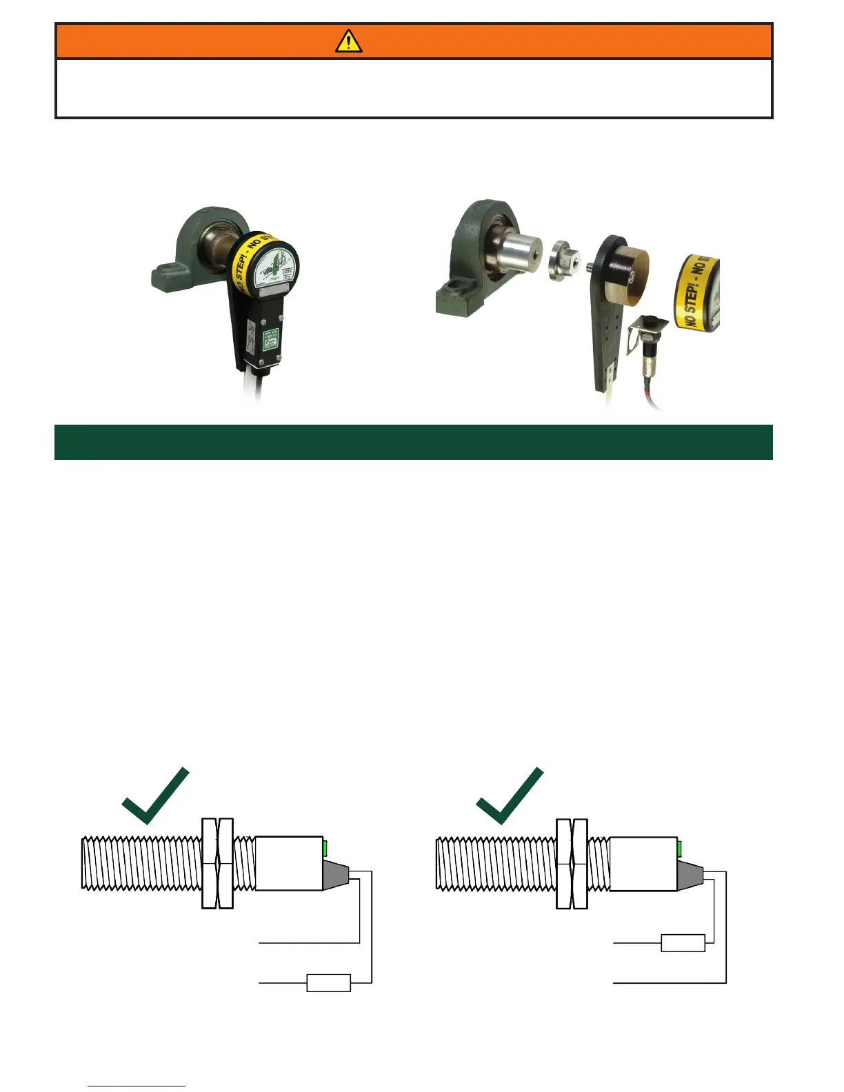
The M100 has a two wire cable. It must be wired through a load (see below) with the same voltage rating
as the supply being used. The supply polarity to the M100 is not important and the load can be connected
to either wire. The cable can be extended to virtually any length with ordinary 2 wire cable.
Do not wire the M100 directly to a motor starting coil due to the 50 mA maximum current capacity.
Blue (L / +V)
LOAD
Supply
24 to 240
Volts AC/DC
Black (N / 0V)
CORRECT
LOAD
Blue (L / +V)
Supply
24 to 240
Volts AC/DC
Black (N / 0V)
CORRECT