2 Front & Rear Panel
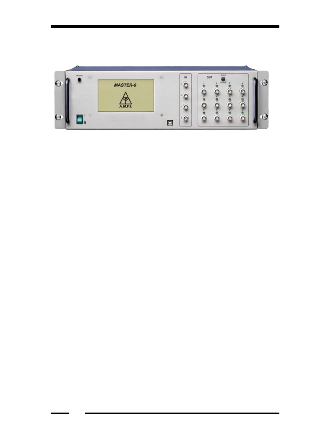
Figure 1
2.1 Front panel
The front panel consists of the following sections (see Figure 1):
Power Switch - located on the left side of the front panel.
Touchscreen (TS) - where the Master-9 parameters can be viewed and modified (Chapter 3).
Backlight switch - turns the TS backlight on & off..
Stylus pen - located at the bottom of the Master-9, under the power switch.
USB interface – used for:
Communicating and programming of the Master-9 by using a computer (Chapter 14).
Upgrading the Master-9 (firmware upgrades, Chapter 14).
Input section. The input section has 4 BNC sockets:
IN 1, 2, 3 inputs are used to externally trigger channels 1, 2 and 3 (Chapter 9).
IN 9 is an analog input for the recording channel 9 (Chapter 13).
Output Section:
a. Enable/Disable Switch - enables/disables all outputs of Master-9. This switch is useful
for cases where immediate stop of the stimulation is required. Make sure that this switch
is set to ENABLE.
b. 12 output BNC sockets and LEDs - Each of the 9 channels has an output BNC socket
and a LED that indicates the channel activity. There are 3 additional outputs A, B and C
for output combinations of the 9 channels.
2.2 Rear panel
The rear panel contains a switch to connect or disconnect the ground to/from the chassis.
This switch can be used to reduce the noise level of the system.
 Loading...